4.2.5. PID Autotuning in MATLAB
This section is yet to be written. In the meantime, please review this detailed tutorial from the Control Systems Tutorial in MATLAB and Simulink.
4.2.5.1. MATLAB’s PID Block
MATLAB has introduced a PID block that can be used either from the command-line or within Simulink. The benefit of this block is that it can be used to autotune the PID compensator parameters in-loop.

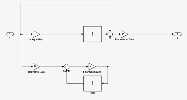
The continuous-time PID block is to be found in the Continuous Systems library in Simulink. The block diagram is as shown below.

The transfer function of the PID is
which reduces to
By comparison with the standard PID
where $\(P = K_\mathrm{prop}\)$
There is an extra pole at \(s = -N\) which is there to limit the high-frequency gain of the Proportional+Derivative term.
In addition to the pole at the origin which is introduced by the integral term, The MATLAB PID has a proportional gain, two zeros, and an additional pole. Thus there are four parameters which can be adjusted to give a range of possible structures.
4.2.5.2. Autotuning the PID
Let us repeat the previous example (See 4.2 Manual Tuning).
Here we have:
and we ended up with
with \(K_{\mathrm{prop}} = 19\), \(T_D = 4/19\), \(T_I = 2\).
Setting the PID with the equivalent values
imatlab_export_fig('print-svg') % Static svg figures.
P = 19; D = 4/19; I = 2;
D = pidstd(P, I, D)
D =
1 1
Kp * (1 + ---- * --- + Td * s)
Ti s
with Kp = 19, Ti = 2, Td = 0.211
Continuous-time PID controller in standard form
In MATLAB we use
s = tf('s');
G = 1/(5*s^2 + 6*s + 1)
G =
1
---------------
5 s^2 + 6 s + 1
Continuous-time transfer function.
Go = series(D,G)
Go =
4 s^2 + 19 s + 9.5
------------------
5 s^3 + 6 s^2 + s
Continuous-time transfer function.
Gc = feedback(Go,1)
Gc =
4 s^2 + 19 s + 9.5
---------------------------
5 s^3 + 10 s^2 + 20 s + 9.5
Continuous-time transfer function.
step(Gc)
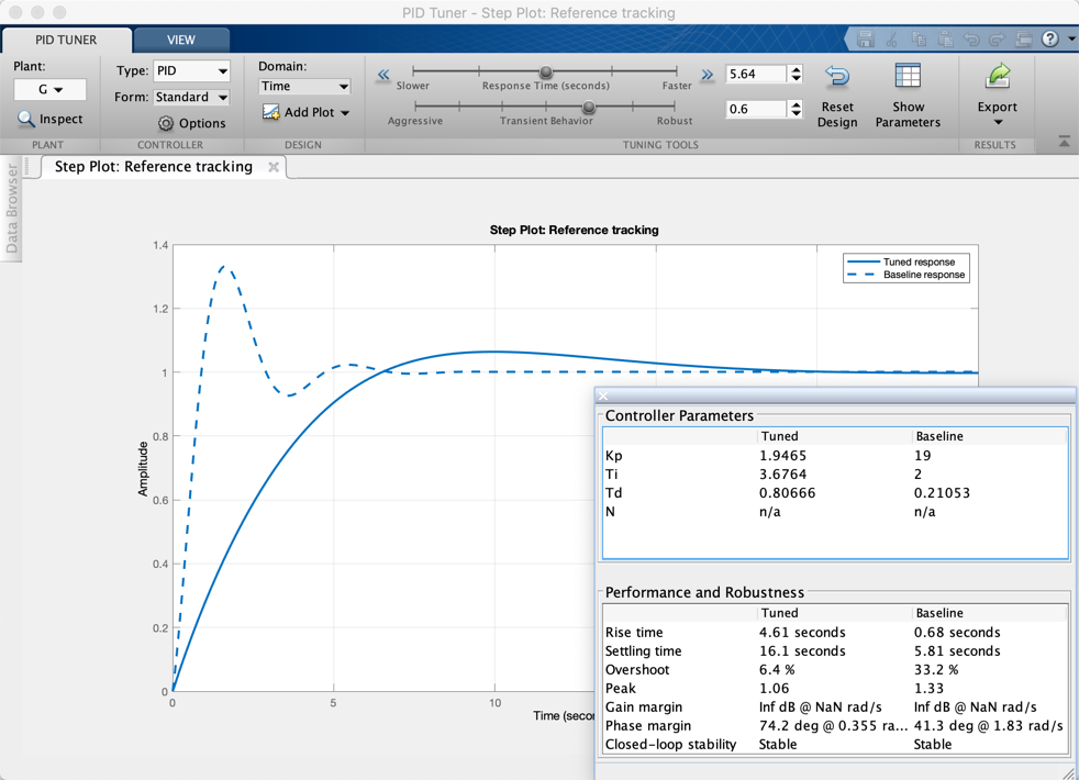
We can now use this design as a baseline for autotuning the PID
pidTuner(G,D)
Results are:

