Voltmeter
Brief: Build a Voltmeter using the Arduino Nano processor and the 16 by 2 LCD.
The Voltmeter must, as a minimum, display voltage in at least one range, with units, decimal points, included on the display. This will require additional circuitry in the form of potential dividers and protection diodes to prevent over voltages from damaging the Arduino Nano.
Marks will be awarded as follows:
0 to 40%: For a non-functional unit which shows signs of working.
40 to 50%: For a minimal implementation of the specification, displaying a number which is at least proportional to the applied voltage.
50 to 60%: For a correctly calibrated voltmeter with decimal points and units displayed.
60 to 70%: For a voltmeter displaying plus and minus voltages.
70% plus: This mark will only be given to a voltmeter with some additional functionality, such as multiple ranges, auto ranging, zero offset, memory and so on.
Technical Information
Here is a video of Dr. Davies explaining how to begin the Voltmeter Mini-Project
Initial calibration of voltmeter:
Assume \(V_\mathrm{ref} = 5\)V.
Let us have a resistive network which divides \(V_\mathrm{in}\) by four, so 20 V in becomes 5 V after the network.
In order to display the voltage as a meaningful number, and remembering that the maximum input to a 10 bit ADC produces a digital number of 1023, let us divide by 1024 and multiply by 20, using floating point numbers.
\[\frac{V_\mathrm{in}}{1024}\times 20\]
This resulted in reading of \(7.388\) for an input of \(7.06\) which was about 6% in error.
The value of \(V_\mathrm{ref}\) was measured using a voltmeter, and found to be \(4.73\)V, not 5V. So the program was modified to multiply by \(18.92\) and divide by \(1023\). This resulted in an error of about 1%, which is much better!
The demo code which accounts for these adjustments follows:
/*
  LiquidCrystal Library - Hello World

  Demonstrates the use a 16x2 LCD display.  The LiquidCrystal
  library works with all LCD displays that are compatible with the
  Hitachi HD44780 driver. There are many of them out there, and you
  can usually tell them by the 16-pin interface.

  This sketch prints "Hello World!" to the LCD
  and shows the time and the value of analogue input A7

  The circuit:
   LCD RS pin to digital pin 8
   LCD Enable pin to digital pin 9
   LCD D4 pin to digital pin 4
   LCD D5 pin to digital pin 5
   LCD D6 pin to digital pin 6
   LCD D7 pin to digital pin 7
   LCD R/W pin to ground
   LCD VSS pin to ground
   LCD VCC pin to 5V
   10K resistor:
   ends to +5V and ground
   wiper to LCD VO pin (pin 3)
   analogue input to Nano A7

  Library originally added 18 Apr 2008
  by David A. Mellis
  library modified 5 Jul 2009
  by Limor Fried (http://www.ladyada.net)
  example added 9 Jul 2009
  by Tom Igoe
  modified 22 Nov 2010
  by Tom Igoe
  modified 7 Nov 2016
  by Arturo Guadalupi
  this sketch modified 24th Nov 2021
  by Timothy Davies


*/

// include the library code:
#include <LiquidCrystal.h>

// initialize the library by associating any needed LCD interface pin
// with the arduino pin number it is connected to
const int rs = 8, en = 9, d4 = 4, d5 = 5, d6 = 6, d7 = 7;
LiquidCrystal lcd(rs, en, d4, d5, d6, d7);

// define the left and right push buttons
const int left = 11, right = 10;

float ADC_READING = 0;

void setup() {
  // set up the LCD's number of columns and rows:
  lcd.begin(16, 2);

// Print a message to the LCD.
  lcd.print("Voltmeter demo");

  pinMode(left, INPUT_PULLUP);
  pinMode(right, INPUT_PULLUP);
}

void loop() {
  // set the cursor to column 0, line 1
  // (note: line 1 is the second row, since counting begins with 0):
  lcd.setCursor(0, 1);

  // print the number of seconds since reset:
  lcd.print(millis() / 1000);

  //move the cursor to the middle of the second line
  lcd.setCursor(4, 1);

  //print the message with extra spaces to blank previous analogue data
  lcd.print("Vin =     ");

  //move the cursor to the printing position for the analogue data
  lcd.setCursor(10, 1);

  // First attempt at calibration:
  // The analogue input gives a number 0 to 1023
  // Let us multiply by 20 and divide by 1024 to
  // give us a number scaled 0 to 20 V instead

  // Second attempt at calibration:
  // Let us multiply by (4.73 times 4) instead of 20,
  // And divide by 1024.

  ADC_READING = analogRead(7);
  ADC_READING = ADC_READING*18.92; // (4*4.73)
  ADC_READING = ADC_READING/1023;
  lcd.print(ADC_READING);

  if (digitalRead(left) == 0)
  {
    lcd.setCursor(14, 0);
    lcd.print("L");
  }
  else if (digitalRead(right) == 0)
  {
    lcd.setCursor(14, 0);
    lcd.print(" R");
  }
  else {
    lcd.setCursor(14, 0);
    lcd.print("  ");
  }
  delay(100);
}
View and download the code from GitHub gist voltmenter.ino.
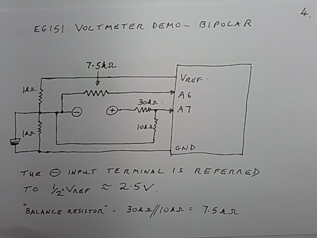
Bipolar Voltage Measurement
Here is some additional information for students who have chosen this mini-project.
What follows is a short video on how to measure and display bipolar (plus and minus) voltages.
Some stills from the video:
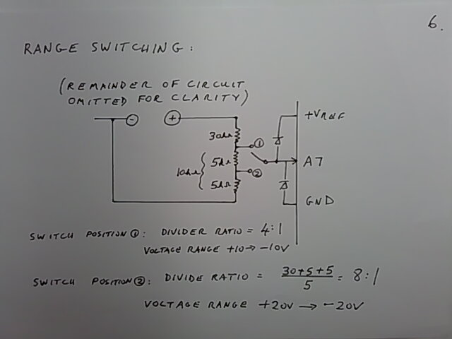
Range switching
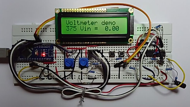
Prototype bipolar voltage management
Code used in this demonstration:
/*
  LiquidCrystal Library - Hello World

  Demonstrates the use a 16x2 LCD display.  The LiquidCrystal
  library works with all LCD displays that are compatible with the
  Hitachi HD44780 driver. There are many of them out there, and you
  can usually tell them by the 16-pin interface.

  This sketch prints "Hello World!" to the LCD
  and shows the time and the value of analogue input A7

  The circuit:
   LCD RS pin to digital pin 8
   LCD Enable pin to digital pin 9
   LCD D4 pin to digital pin 4
   LCD D5 pin to digital pin 5
   LCD D6 pin to digital pin 6
   LCD D7 pin to digital pin 7
   LCD R/W pin to ground
   LCD VSS pin to ground
   LCD VCC pin to 5V
   10K resistor:
   ends to +5V and ground
   wiper to LCD VO pin (pin 3)
   analogue input to Nano A7

  Library originally added 18 Apr 2008
  by David A. Mellis
  library modified 5 Jul 2009
  by Limor Fried (http://www.ladyada.net)
  example added 9 Jul 2009
  by Tom Igoe
  modified 22 Nov 2010
  by Tom Igoe
  modified 7 Nov 2016
  by Arturo Guadalupi
  this sketch modified 24th Nov 2021
  by Timothy Davies


*/

// include the library code:
#include <LiquidCrystal.h>

// initialize the library by associating any needed LCD interface pin
// with the arduino pin number it is connected to
const int rs = 8, en = 9, d4 = 4, d5 = 5, d6 = 6, d7 = 7;
LiquidCrystal lcd(rs, en, d4, d5, d6, d7);

// define the left and right push buttons
const int left = 11, right = 10;

float ADC_READING = 0;

void setup() {
  // set up the LCD's number of columns and rows:
  lcd.begin(16, 2);

  // Print a message to the LCD.
  lcd.print("Voltmeter demo");

  pinMode(left, INPUT_PULLUP);
  pinMode(right, INPUT_PULLUP);
}

void loop() {
  // set the cursor to column 0, line 1
  // (note: line 1 is the second row, since counting begins with 0):
  lcd.setCursor(0, 1);

  // print the number of seconds since reset:
  lcd.print(millis() / 1000);

  //move the cursor to the middle of the second line
  lcd.setCursor(4, 1);

  //print the message with extra spaces to blank previous analogue data
  lcd.print("Vin =      ");

  //move the cursor to the printing position for the analogue data
  lcd.setCursor(10, 1);

  // Calibration:
  // Let us multiply by (4.73 times 4) instead of 20,
  // And divide by 1024.

  ADC_READING = analogRead(7) - analogRead(6);
  //ADC_READING = ADC_READING*18.92;
  ADC_READING = ADC_READING * 18.71;
  ADC_READING = ADC_READING / 1023;
  if (ADC_READING >= 0) {
    lcd.print(" ");
  }
  lcd.print(ADC_READING);

  if (digitalRead(left) == 0) {
    lcd.setCursor(14, 0);
    lcd.print("L");
  } else if (digitalRead(right) == 0) {
    lcd.setCursor(14, 0);
    lcd.print(" R");
  } else {
    lcd.setCursor(14, 0);
    lcd.print("  ");
  }
  delay(100);
}
Copyright © 2021-2024 Swansea University. All rights reserved.