1 Introduction to Microcontrollers and Microcontroller Architecture
Presentation version of these notes.
50 years of teaching microprocessors at Swansea!

A brief history by our former colleague, Honoury Lecturer Dr Timothy Davies.
- Started in 1972/1973 by Prof. David Aspinall and Dr. Erik Dagless, using bespoke equipment based on the Intel 8008.
- Always using 8-bit micros such as Intel 8008, Intel 8085, Motorola 68HC11, Motorola 68HCS08…
- Take-home lab, developed by Dr Davies, in 2020, used the Arduino Nano which is based on the Atmel (now MicroChip) ATmega328
- One of our former students, Prof Sir Andy Hopper, asked why we are not teaching using the ARM processor which he helped develop.
- Spring 2021 - the launch of a new microcontroller, the RP2040 which is packaged into a small module, costing only three pounds.
- This is the microcontroller for our second-year EG-252 lab and is also used in the third-year module EG-3082 Embedded Systems launching this year,
- You will therefore be using microcontrollers throughout this program
Introduction
In this week’s lecture, you will be given an introduction to microcontrollers focusing on what a microcontroller is, where they can be found and how they can be described using the their architecture. The lecture then moves on to introduce the Atmel ATmega328 microcontroller, which will be used in the practical sessions in this course, looking at its core architecture including the function of the arithmetic logic unit and registers.
Topics Covered in this Lecture
1.1 What is a Microcontroller?
A microntroller is a compact integrated circuit designed to govern a specific operation or set of operations within an embedded system.
At a high level of abstraction, a microntroller includes three core components within a single chip:
- A central processing unit (CPU)
- Memory, and
- Input/output (I/0) peripherals
1.2 Where are Microcontrollers Used?
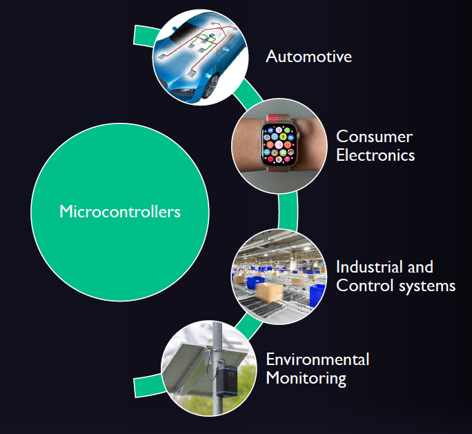
Microcontrollers are used in the automotive industry, consumer electronics, industrial and control systems, and environmental monitoring and many other areas of engineering.
1.2.1 Automotive applications
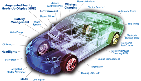
Applications of microcontrollers in the automotive industry
|
|
1.2.2 Consumer electronics
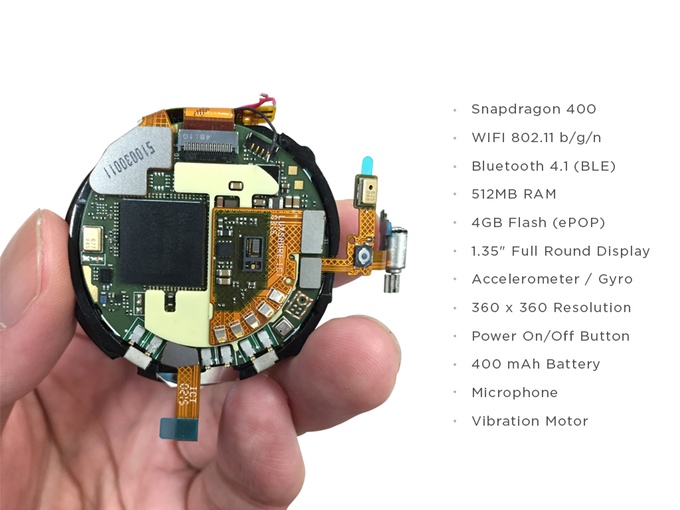
Applications of microcontrollers in consumer electronics
|
|
1.2.3 Industrial applications

Applications of microcontrollers in manufacturing systems
|
|
1.2.4 Environmental monitoring
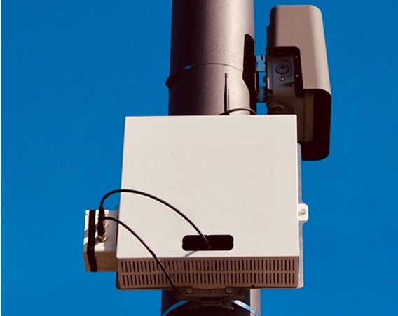
Applications of microcontrollers in environmental monitoring
|
|
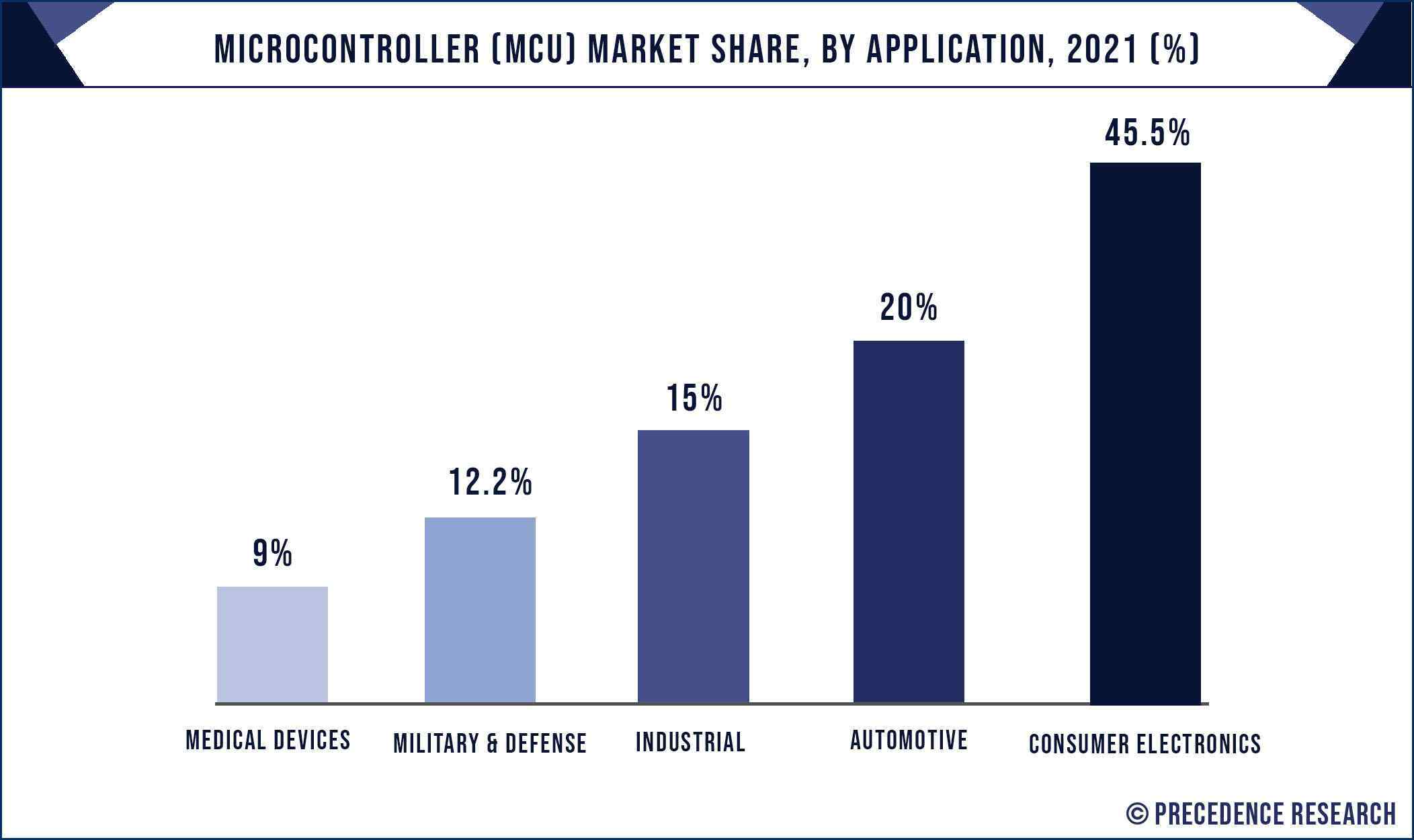
1.2.5 Microcontroller Market Forecast
1.3 How do we Describe Microcontrollers?
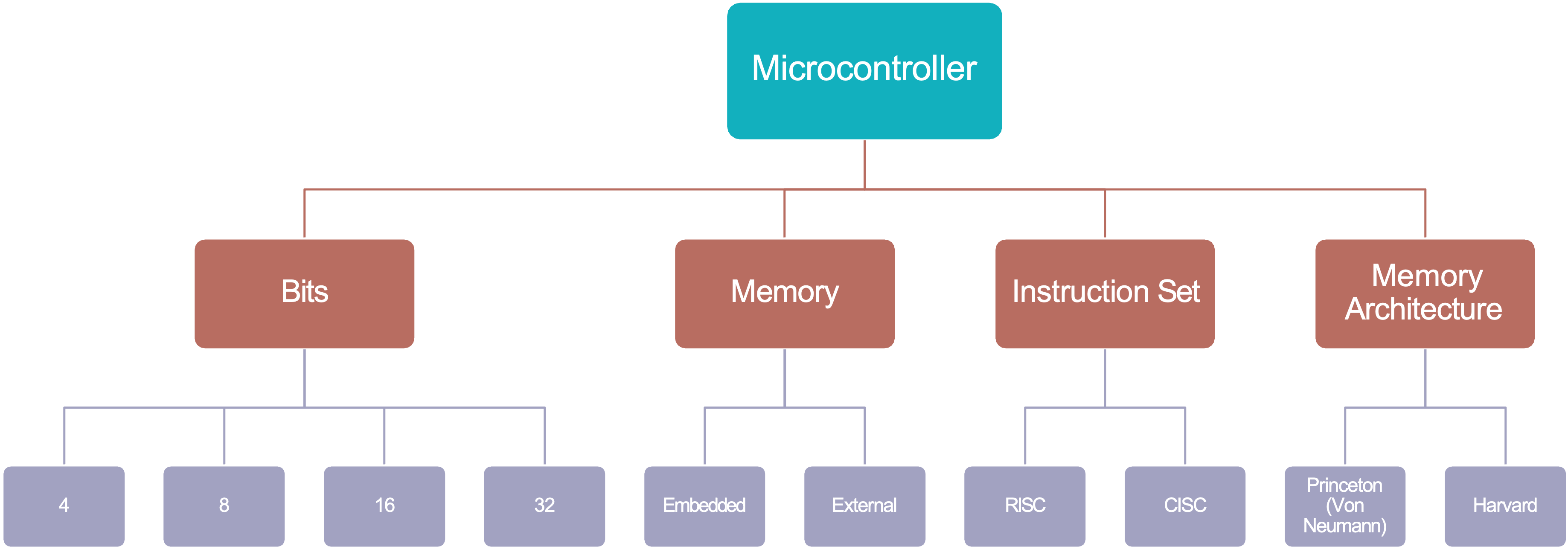
1.3.1 Architecture
Definition from the Oxford English Dictionary architecture
Computing. The conceptual structure and overall logical organization of a computer or computer-based system from the point of view of its use or design; a particular realization of this6.
1.3.1.1 Number of Bits
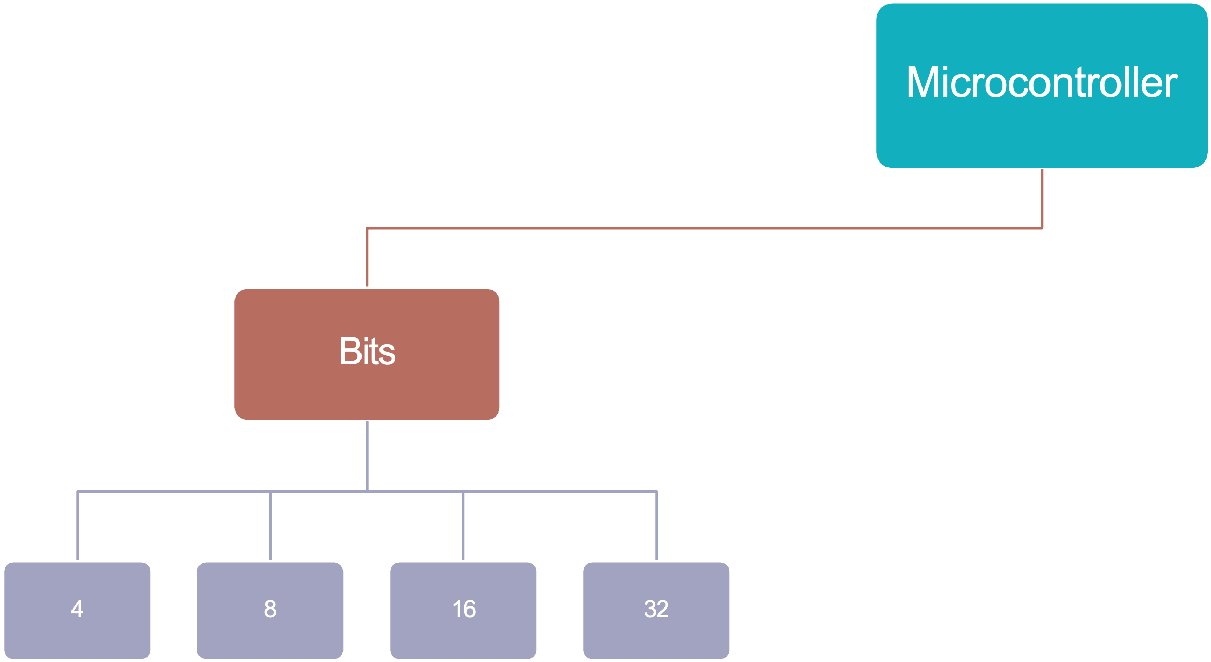
Categorizing Microcontroller Units (MCUs) as 8-, 16-, or 32-bit designs is one way of classifying their performance capabilities.
The number of bits identifies the size of the registers, the number of available memory addresses and the largest number that can be processed/represented.
As an example, in an 8-bit MCU
- Each register is 8-bits (or one byte) wide.
- There are \(2^8\) (or 256) possible memory addresses
- There are \(2^8\) integers that can be represented (0 to 255).
Microcontrollers with more bits, for example 16- and 32-bit MCUs have correspondingly more bits per register, more available memory addresses, and can handle larger numbers compared with their 8-bit counterparts.
An introduction to data representation follows in Introduction to Data Representation.
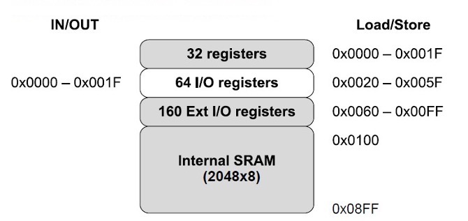
Figure 1.8 shows the data memory map of the Atmel Atmega328 which is an 8- bit MCU.
It has \(2^8\) or 256 available memory addresses from 0x0000 – 0x00FF which covers:
- 32 general purpose registers,
- 64 I/O registers, and
- 160 Extended I/O registers
Applications of 8-bit and 32-bit MCUs
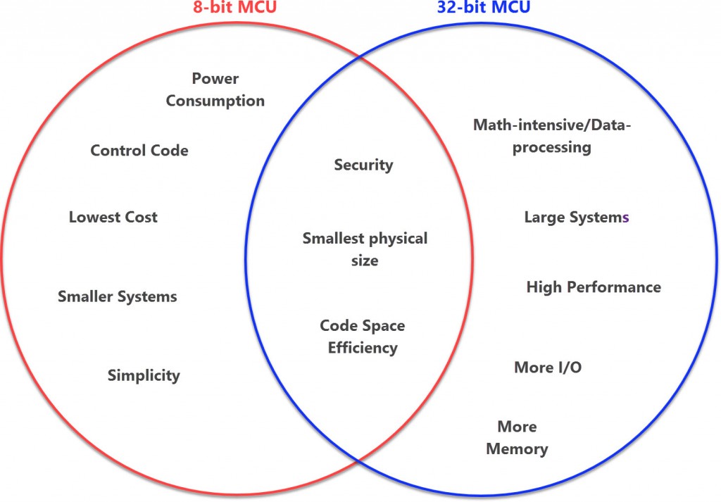
The plotting of the application benefits of the 8-bit MCU vs. the 32-bit MCU is best plotted on a Venn diagram as direct comparisons of all features combined are relative to tradeoffs. In general, the 8-bit MCU has been lower cost and smaller in size than the 32-bit MCU, but 32-bit MCUs are close to competing on cost and both have at least one “specimen” of a similarly minute physical size. In overall power consumption, the slower 8-bit MCUs will always trump the faster 32-bit MCUs as long as manufacturers stay on their game.
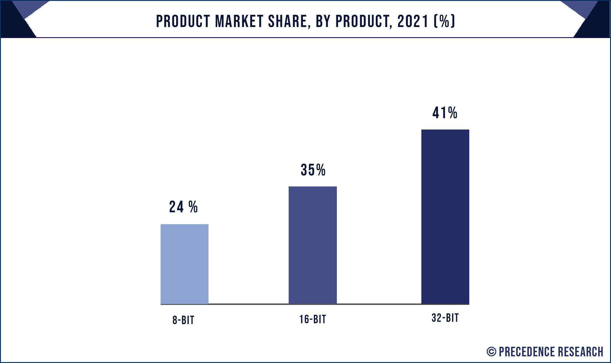
Market share of 8-bit, 16-bit and 32-bit MCUs in 2021
1.3.1.2 Memory
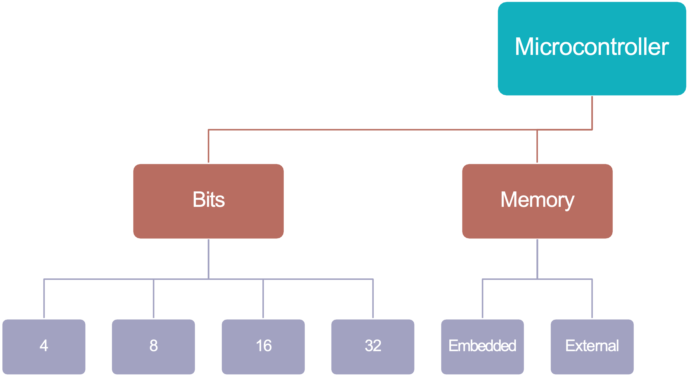
Embedded vs external memory
Memory in modern microcontrollers can be classified as embedded or external dependent on whether this is physically located within the MCU itself or is connected separately.
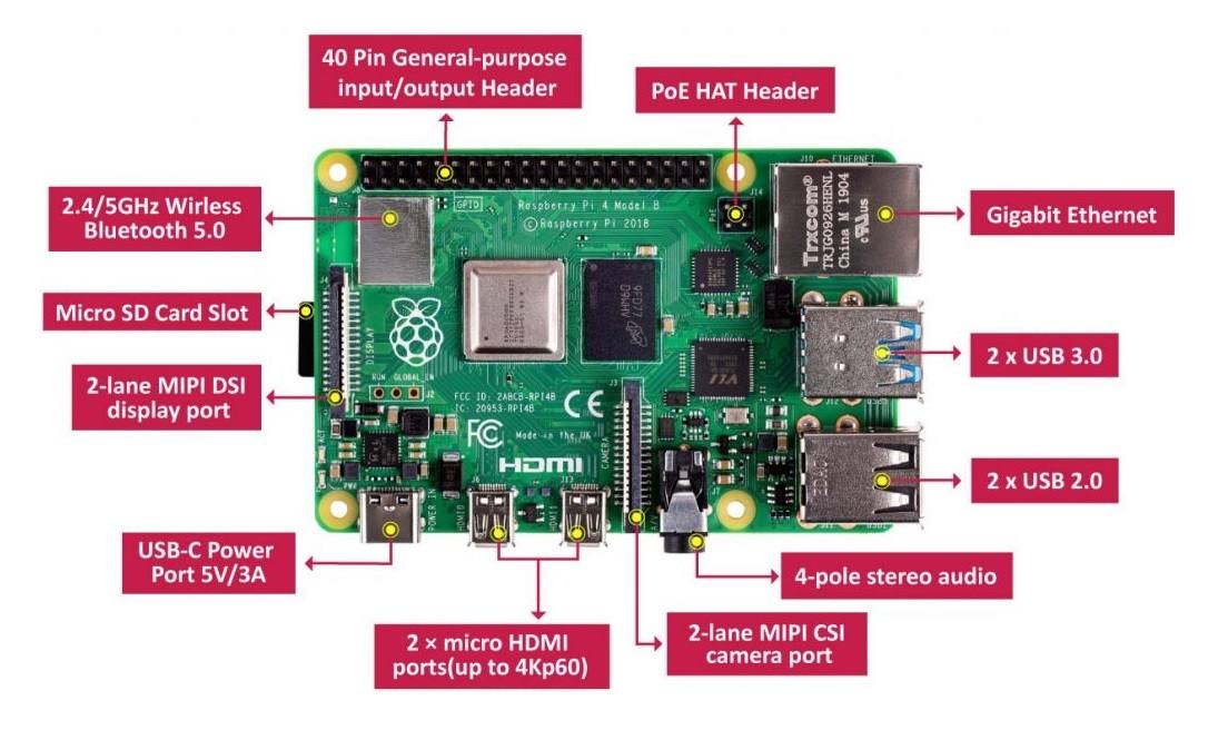
For most microcontroller-based applications, the internal memory is enough. However, applications which gather or buffer large amounts of data may also need external memory in the form of SD cards, M.2 drives and similar.
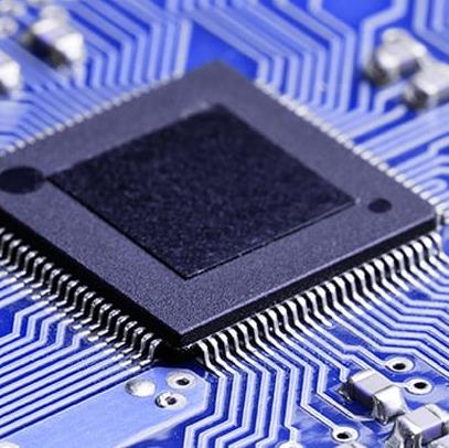
A Raspberry Pi 4 Model B is illustrated in Figure 1.12. It has both internal and external memory.
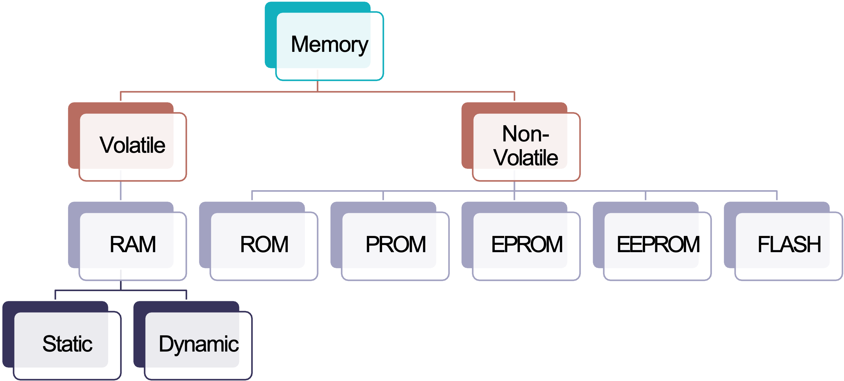
Volatile vs non-volatile embedded memory
Broadly speaking embedded memory that is found in a microcontroller can be classified into two categories:
- Volatile: data is lost when power is removed – this is temporary storage.
- Non-volatile: data is retained when power is removed – this is permanent storage.
Volatile and non-volatile memory can be further classified as illustrated in Figure 1.13.
1.3.1.3 Instruction Set Architectures
Architecture diagram showing instruction sets used in microcontrollers
The instruction set architecture (ISA) describes the format and operation of instructions the microcontroller can perform and a microcontroller will often be categorized as having a RISC based or CISC based architecture.
Reduced instruction Set Computer (RISC)
A RISC is a device with a small, highly optimized set of instructions which utilizes registers and a highly regular instruction pipeline, allowing instructions to be completed in a low number of clock cycles.
In short, several instructions may need to be run to perform a task and this may complicate the coding.
Complex Instruction Computer (CISC)
A CISC is a device in which single instructions can execute several low-level operations or are capable of multi-step operations or addressing modes within single instructions.
In CISC machines, a program may be easier to read by a human, but the timing will be irregular and difficult to debug or be monitored by a machine.
Example
As an example, consider the case where you want to multiply two numbers stored at addresses 0x0010 and 0x0011 respectively.
On a RISC based architecture microcontroller the code would look something like:
However, on a CISC based architecture machine the multiply instruction may be able to perform the memory access instructions within its execution, meaning the code would look like this:
1.3.1.4 Memory Architectures
Memory architecture is a different concept from embedded and external and volatile and non-volatile memory. Memory architecture classifications describe where program instructions and data are stored and how they are accessed.
There are two categories, Von-Neumann and Harvard.
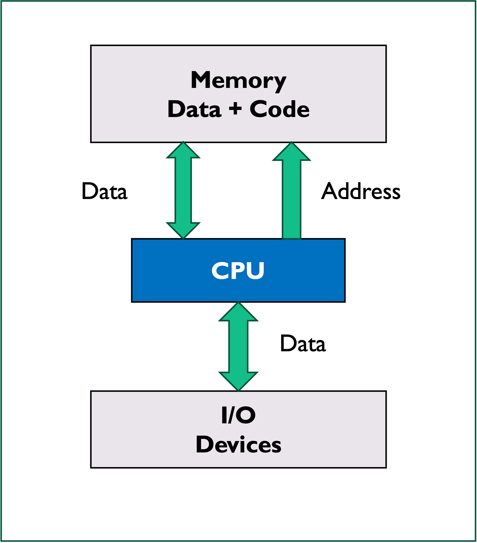
Von-Neumann (Princeton) architecture
In a Von-Neumann architecture, the same memory and bus are used for both data and instructions used by the CPU and peripherals as illustrated in Figure 1.15.
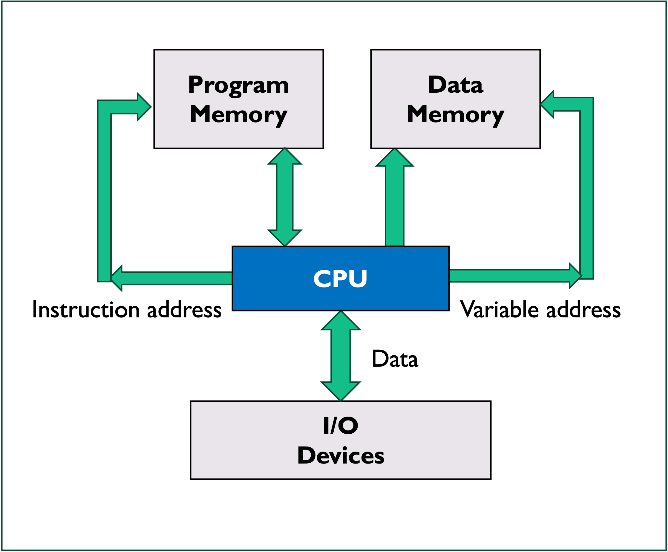
Harvard architecture
The Harvard architecture stores machine instructions and data in separate memory units that are connected to the CPU and peripherals by different busses as illustrated in Figure 1.16.
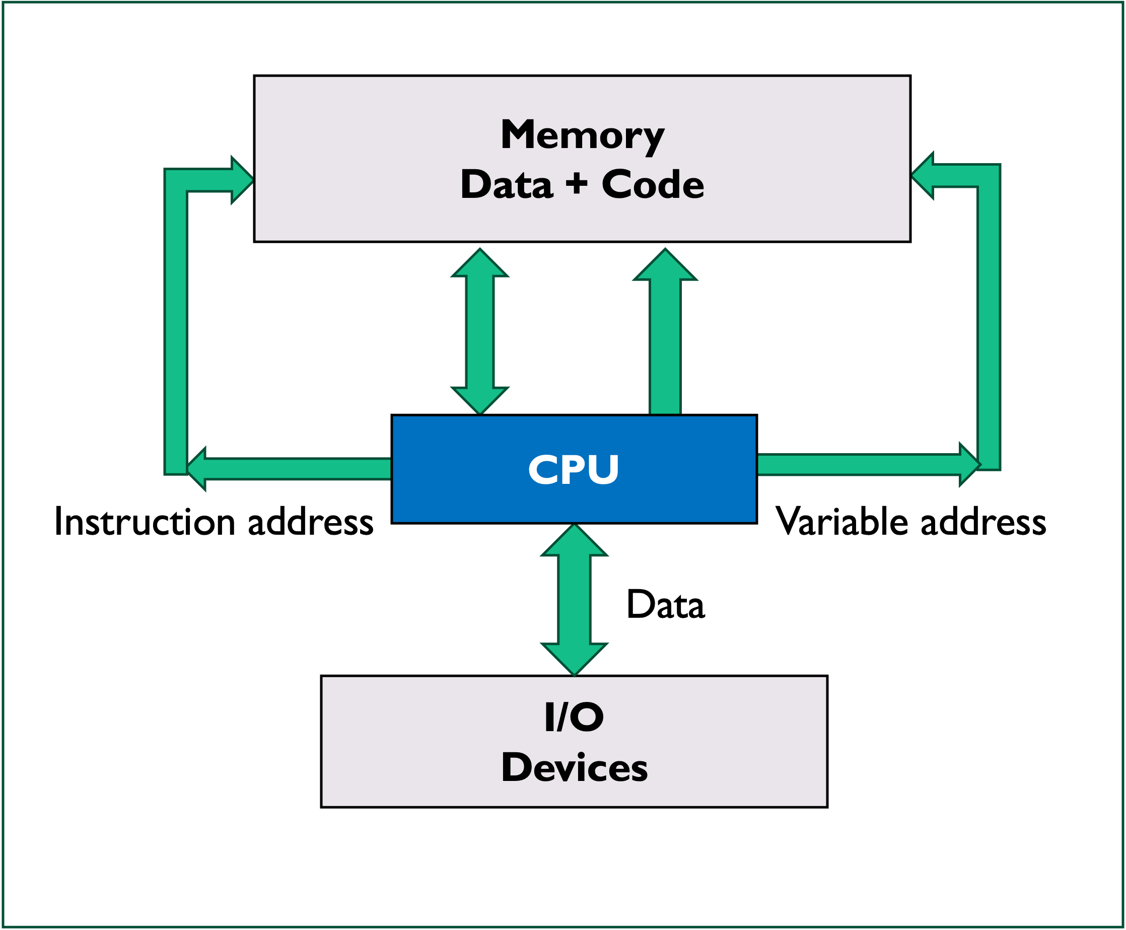
Modified Harvard architecture
Most modern microcontrollers don’t have a physical separation between the memory spaces used by data and instructions, and therefore could be described as Von Neumann for this reason. However, since these microcontrollers often use separate busses for data and instructions as illustrated in Figure 1.17, a better way to represent these is as a modified Harvard architecture10.
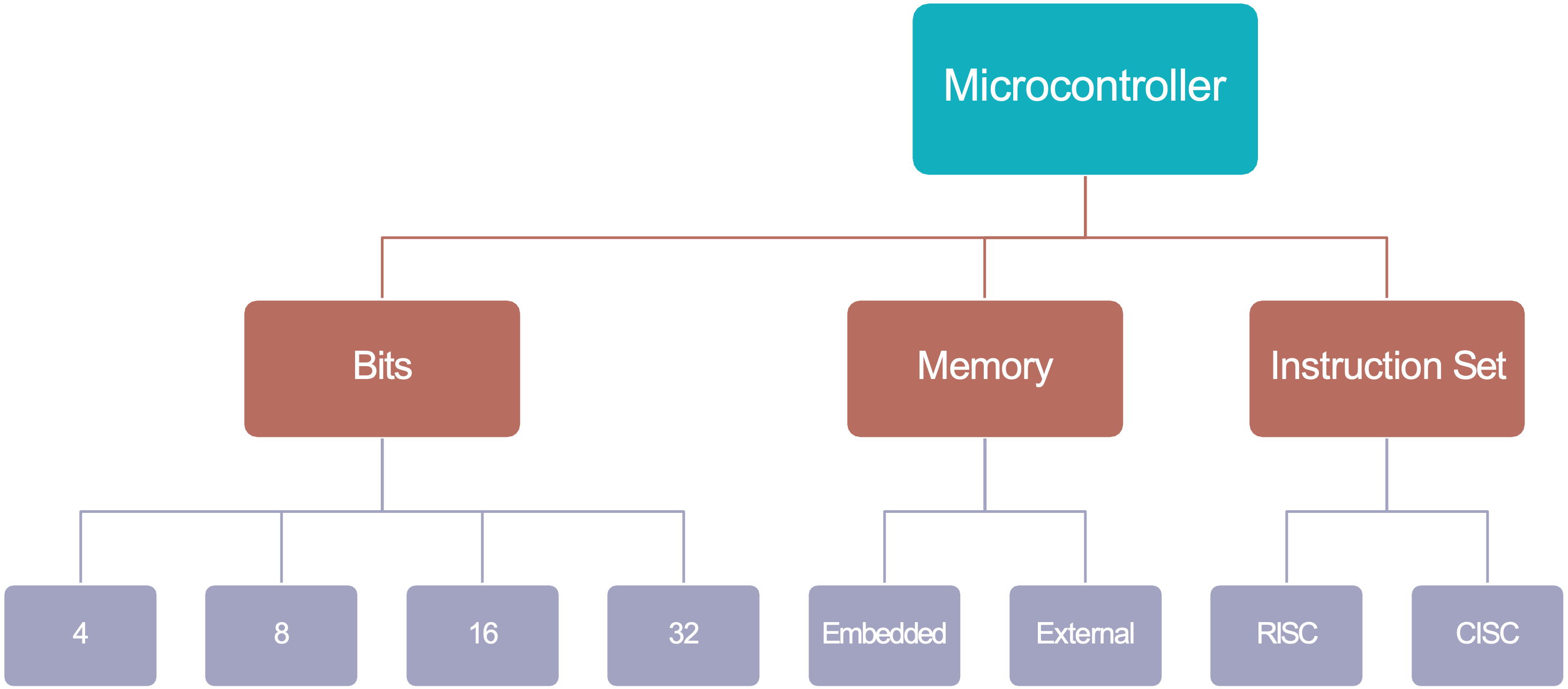
1.3.2 How is a Microcontroller Described?
In summary, the final MCU classification shown in Figure 1.18 represents some of categories under microcontroller architecture which are focused around the system itself.
There are further classifications as you move towards either the circuit design or the embedded system application.
1.3.2.1 System or Core Architecure
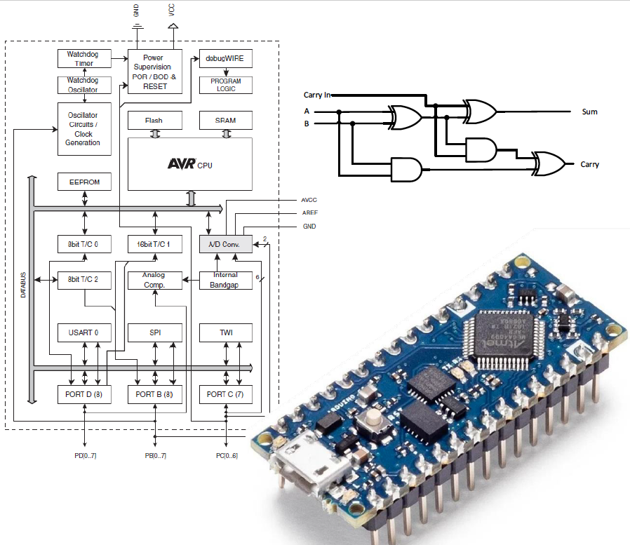
In general, most microcontroller manufacturers will present a system wide, or core architecture in the form of a diagram which will appear early on in the data sheet for the device.
Atmel ATMega328P AVR
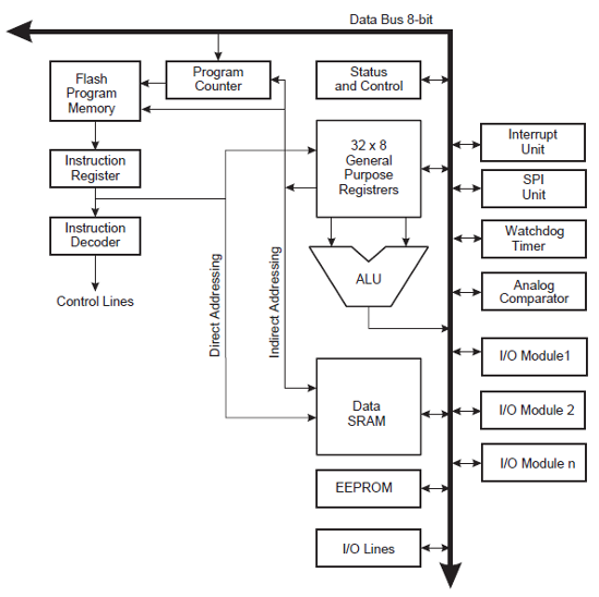
For example, Figure 1.19 is taken from Atmel ATMega328 data sheet (Atmel 2015) and shows a block diagram of the Advanced Virtual RISC (AVR) architecture.
NXP HCS08 MCU
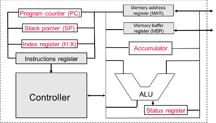
As another example, the block diagram shown in Figure 1.20 represents the architecture of the NXP (formally Motorola) HCS08 MCU.
This MCU, which was used on this module before the Arduino was adopted, does not have a bank of general purpose registers. Instead it has a single working register, known as the accumulator, which is involved in most computations that the MCU performs.
1.4 The Atmel ATmega 328 Microcontroller

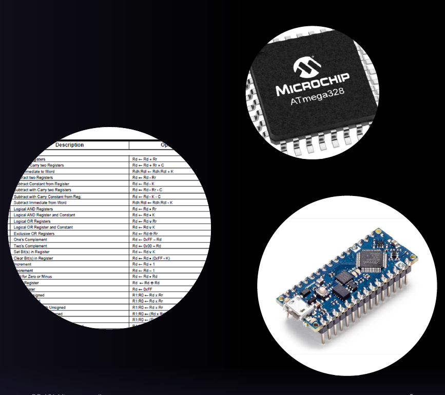
1.4.1 Introducing the Atmel ATMega328 MCU
This is an 8-bit CMOS microcontroller based on the AVR® enhanced RISC architecture with 131 instructions.
It has 2KB of Internal SRAM, 32 KB of Flash Memory and 1 KB of EEPROM.
It has 32 General Purpose Registers.
It can achieve up to 20 MIPS at 20 MHz (maximum clock frequency).
There are 8 Analog I/O pins connected to 10-bit analogue to digital converter (ADC).
There are 22 Digital I/O pins (6 capable of pulse-width modulation (PWM)).
The AVR core uses a Harvard memory architecture – with separate memories and busses for program and data.
1.4.1.1 Arithmetic Logic Unit
The Arithmetic Logic Unit (ALU) (Figure 1.22), is the part of the processor that performs arithmetic and logic operations on numbers from the storage area – it is essentially the “brain” of the microcontroller.
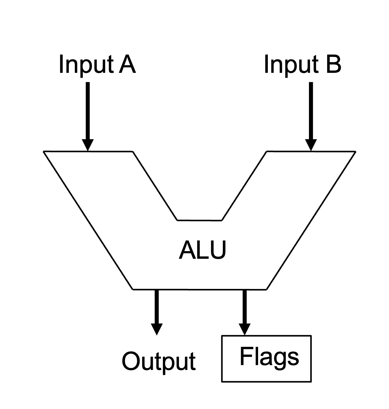
Operation of the ALU
First, numbers are read from storage into the ALU’s data input ports.
Once inside the ALU, they’re modified by means of an arithmetic or logic operation (
ADD,SUB,AND,OR…)Flags are set in the Status Register according to the result of the operation.
Finally, the data is written back to storage via the ALU’s output port.
Example instruction
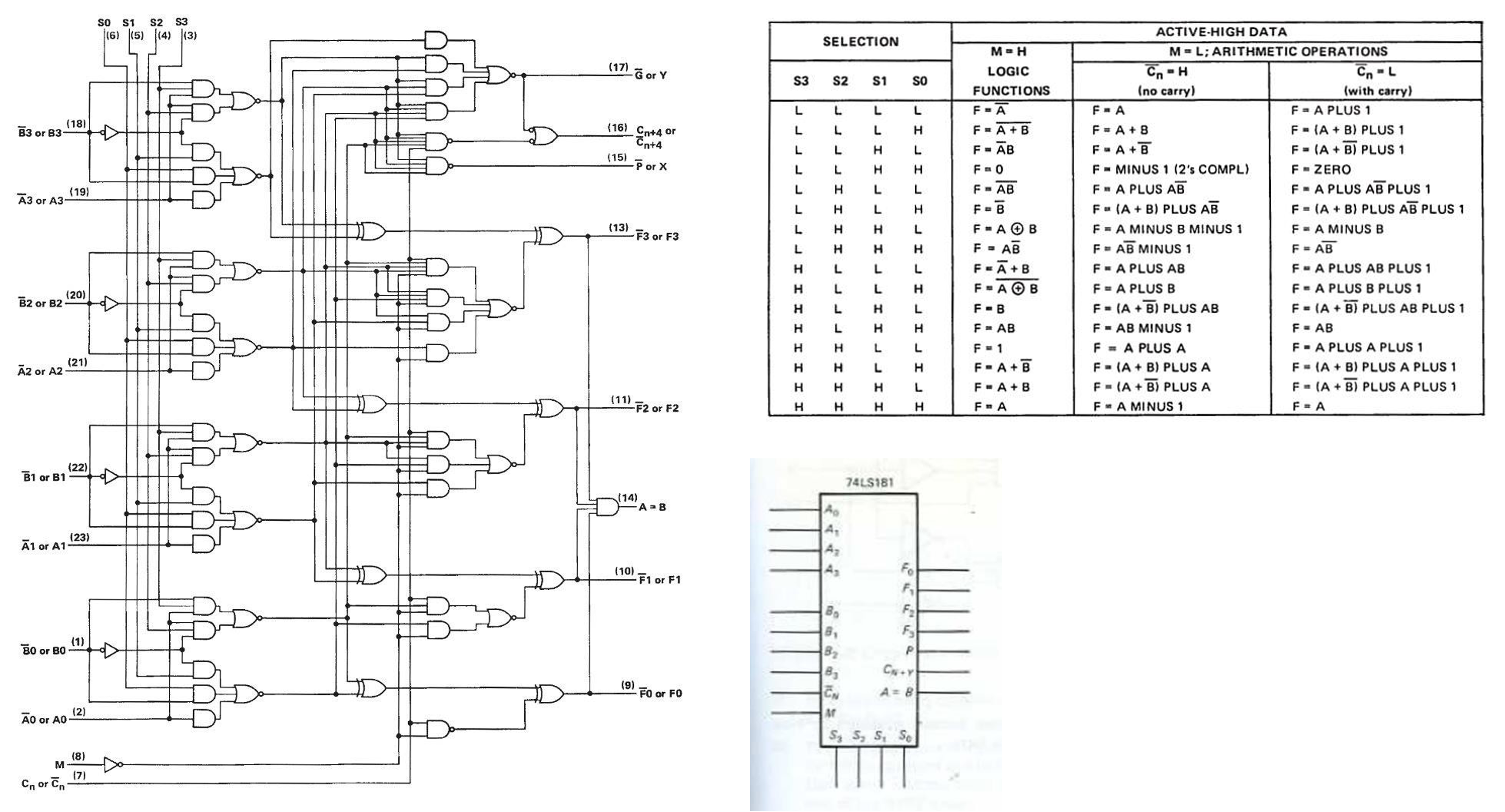
Example of the ALU from the 74LS181
The 74LS181 is a 4-bit microcontroller that supports 16 logical and 16 arithmetic operations.
You do not need to understand Figure 1.24, it is just and example to show that an ALU isn’t just a black box. Rather it contains complex logic circuitry by means of which it performs its operations.
1.4.2 Registers
A register is a group of memory bits with special addressing characteristics which is often used for a particular purpose.
- In most modern processors, regardless of architecture, data is loaded from a larger memory space into special registers where it is used for arithmetic operations, manipulation or testing by various machine instructions.
- Data is then temporarily held in a register until it is overwritten, or the immediate instruction stores it back to main memory.
1.4.2.1 Registers in the ATMega328 MCU
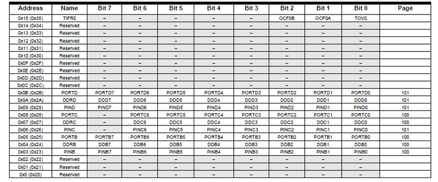
The Atmel ATmega328 is an 8-bit microcontroller and has 256 addressable registers within the user data space. The first 32 locations address the Register File, the next 64 location the standard I/O memory and then the remaining 160 locations for Extended I/O memory.
Figure 1.8 summarizes the memory map of the ATMega328 MCU. Figure 1.26 shows part of the full memory map that is given in the Atmel ATMega280/P data sheet (Atmel 2015, 275–80).
1.4.2.2 The Register File
The register file (see Figure 1.27) contains 32 x 8-bit wide registers that are often referred to as general purpose or working registers in the CPU.
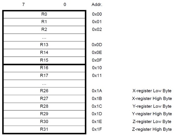
Each register is also assigned a data memory address, mapping them directly into the first 32 locations of the user data space.
Most of the instructions operating on the Register File have direct access to all registers, and most of them are single cycle instructions, however:
R0–R15are not available for all instructions, andR26–R31have some added functions as pointer registers.
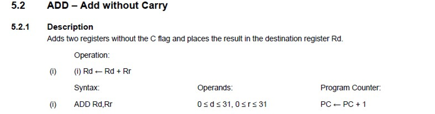
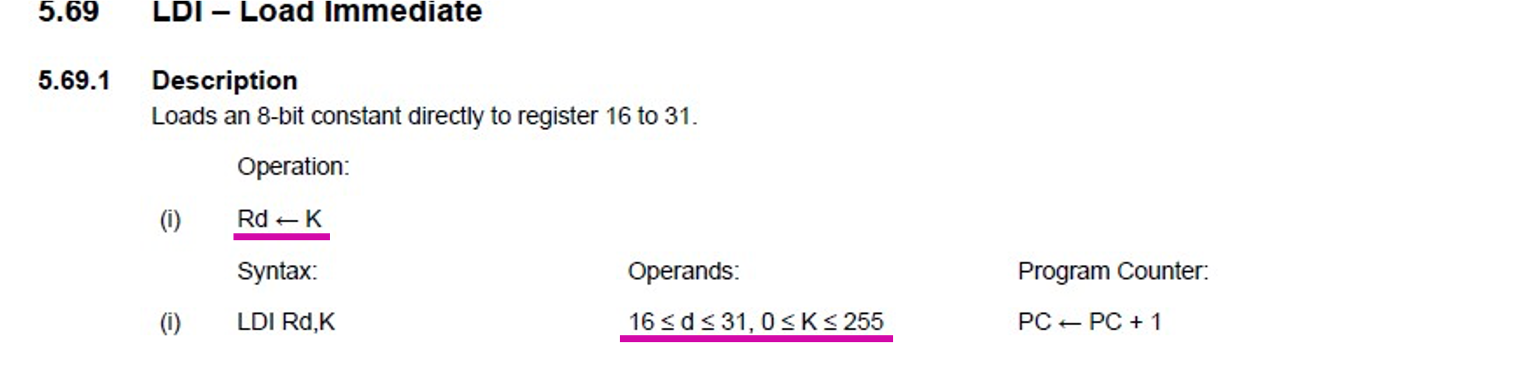
1.4.2.3 Using the Register File
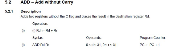
Figure 1.28 shows an extract from the documentation for the use of registers in the add without carry (ADD) operation. Figure 1.29 shows an extract from the documentation for the use of registers for a load immediate (LDI) operation.
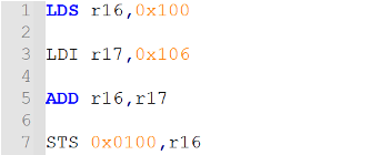
1.4.2.4 X- Y- Z-Pointer Registers
In addition to acting as general purpose registers, R27 - R31 can be used as 16-bit address pointers and referred to as the X-,Y-, Z-registers as illustrated in Figure 1.30. These pointers can be used to indirectly address the SRAM portion of the data space.
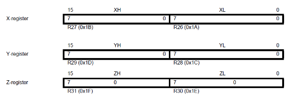
The start address of SRAM is 0x0100, this cannot be accessed with 8-bits (maximum is 0x00FF).
We will look at this in more detail at the end of the module but this approach can be useful to access sets of data where we don’t necessarily know the address.
Summary
In this lecture we have:
Familiarized ourselves with what a microcontroller is and where they are used.
Introduced describing a microcontroller by considering parts of its architecture and
Begun to look at the Atmel ATmega328 microcontroller focusing on its register file and the general-purpose registers.
On Canvas
There is a Canvas quiz which tests your recall of the topics covered in this lecture.
Next week
Next week we will look at Data Representation.
Source of original image used in Figure 1.2: www.linkedin.com/pulse/microcontrollers-used-automotive-applications-field-amin-agina. The original image is no longer accessible.↩︎
Source of image used in Figure 1.3: www.electronicsweekly.com/blogs/distribution-world/communities/innovative-smartwatch-challenges-apples-watch-design-2015-10↩︎
Original source of image used in Figure 1.4: investinfrance.fr/high-technology-industry/robotic-arm-catch-for-electronic-assembly-line-the-robot-for-sm/. This original image is no longer available online.↩︎
Source of image used in Figure 1.5: www.openpr.com/news/1799966/hawa-dawa-installs-the-largest-air-quality-measurement-network↩︎
Source of imaged used in Figure 1.6: www.precedenceresearch.com/microcontroller-mcu-market↩︎
“architecture, n., sense 6”. Oxford English Dictionary, Oxford University Press, July 2023, https://doi.org/10.1093/OED/5575991854↩︎
The source of the Venn diagram used in Figure 1.9: http://lreese.dotsenkoweb.com/2017/07/31/iot-choosing-8-bit-vs-32-bit-mcus↩︎
Source of image used in Figure 1.10: www.precedenceresearch.com/microcontroller-mcu-market↩︎
Source of image used in Figure 1.12: www.hackatronic.com/raspberry-pi-4-specifications-pin-diagram-and-description.↩︎
This gets around the bottleneck that can occur using a Von-Neumann memory architecture with lower costs than having two separate memories.↩︎
Source of Figure 1.21 is BregesT65421354, CC BY-SA 4.0 <https://creativecommons.org/licenses/by-sa/4.0>, via Wikimedia Commons.↩︎
Copyright © 2021-2024 Swansea University. All rights reserved.