Construction Exercise - Continuity Tester
What is a Continuity Tester?
A continuity tester is an essential tool for the electrical engineer. It allows the user to follow wires, printed circuit tracks, and ribbon cables from one end to the other with ease. Bulbs, fuses, motor windings, and transformers, can be tested for continuity. Diode polarity and transistor gain can also be determined with little care. These tests can, of course, be performed using a multimeter, but an audible indication is particularly useful because it is not necessary to look away from the circuit under examination.
Circuit Operation
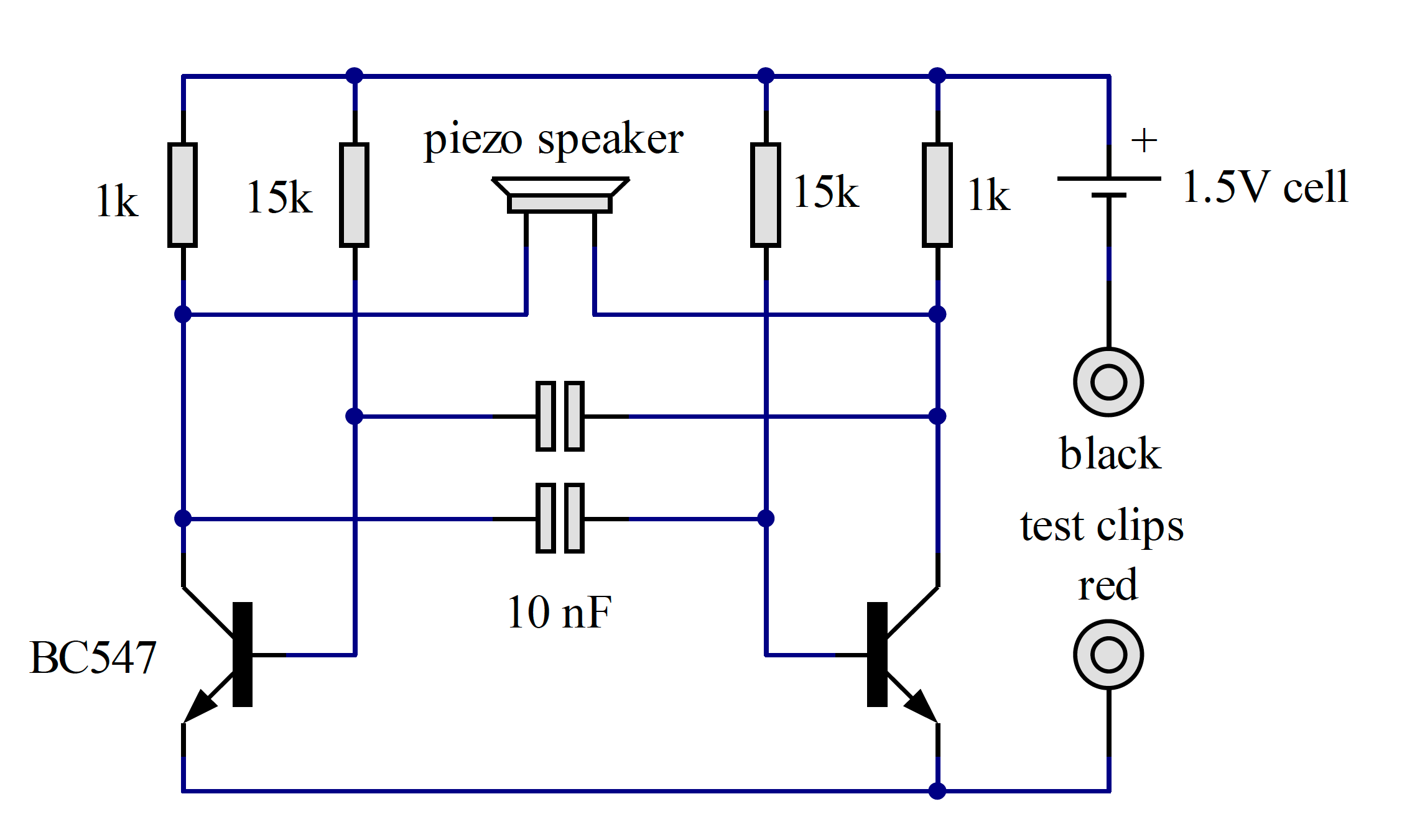
The simplest form of continuity tester is a torch bulb and battery. This can be used to test circuits of low resistance, but for electronic circuits, a low applied voltage and test current is much more suitable. Our tester uses a circuit attributed to a Mr Eccles and a Mr Jordan (see Figure 18.1) and is referred to in textbooks as an “astable multivibrator”. An astable multivibrator consists of two transistors, cross-coupled using resistors and capacitors, which oscillate at a well-defined frequency. The two transistors are switching in antiphase; that is, one is on, and the other is off at any given instant. A loudspeaker connected between the collectors will experience a peak-to-peak voltage of twice the supply, so a low voltage battery can be used and still produce a loud noise. The base resistors and the capacitors control the pitch (frequency) of the sound.
Circuit Construction
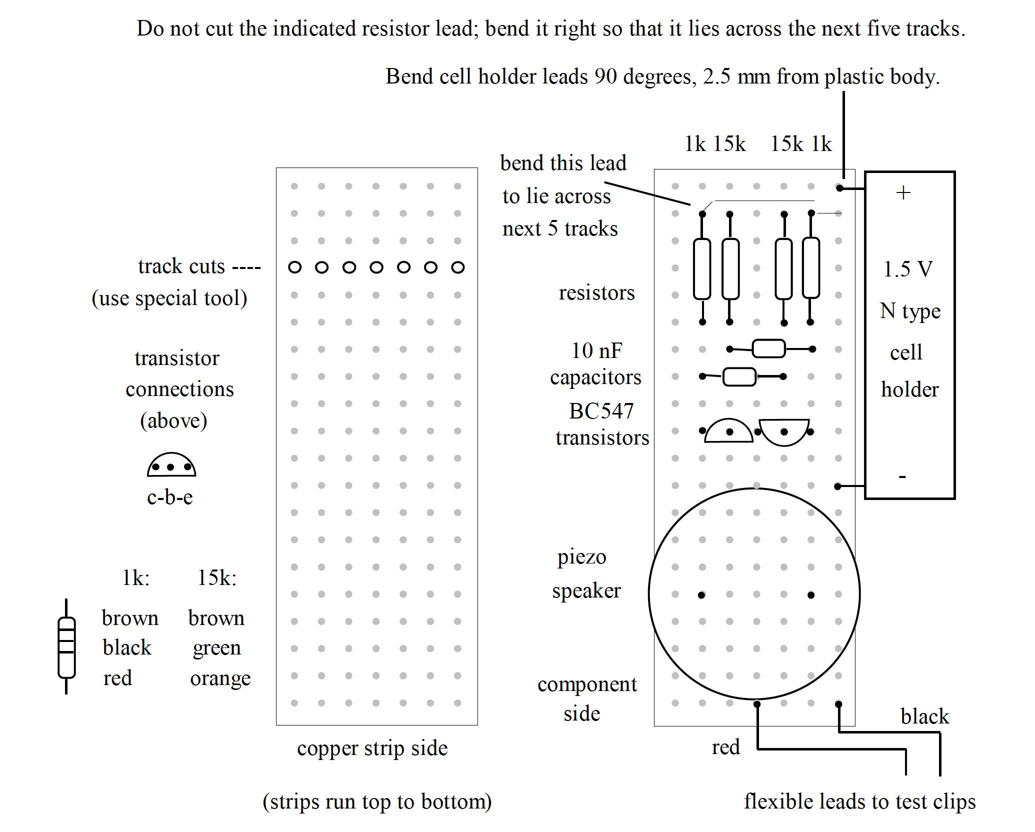
The circuit is symmetrical and suited to construction on stripboard (Veroboard). Stripboard consists of an insulating board with thin copper tracks spaced 0.1 inches apart and perforated with holes on a 0.1-inch grid. Before any soldering, certain tracks must be cut using a special tool. This is a drill bit in a handle and must be used lightly to avoid damaging the board. It is centred on a hole and twisted a half turn so that a thin sliver of copper is removed. Then the cut must be inspected to ensure no “whiskers” of copper remain.
Orient the board as seen in Figure 6.2, looking at the component side. The first component to be mounted is the left-hand 1k resistor. Its leads are bent (using pliers, not by hand!) so that the spacing is 0.4 inches. Then it is fitted onto the board, as shown in {ref}fig8.2, and the leads are bent out slightly so that it does not fall out when the board is inverted. The lead indicated must be bent at right angles so that it lies across the tracks to form a bridge. Bend and insert the right-hand 1k resistor and bend the top lead to form a bridge to the last track. The two 15k resistors are mounted on the board as shown, but their leads will be cut short after soldering. Now the leads can be soldered so that the bent lead bridges the top end of all four resistors. After soldering, cut the remaining resistor leads flush with the board.
Refer to {ref}soldering for instructions on soldering. If you have never used a soldering iron previously, ask one of the demonstrators for help. Make sure you work on one of the extraction mats with the air filter turned on to keep the fumes away from your face.
Identify the two 10nF capacitors. Their leads are deformed to a spacing of 0.2 inches; straighten and re-bend the leads to a spacing of 0.3 inches. Then fit the capacitors as shown and solder them in place. Trim the leads flush with the board.
Next, unpack the two BC547 transistors. Unlike the resistors and capacitors, these components are polarity sensitive and must be wired correctly. Refer to the diagram for the proper orientation. The transistors on the prototype were fitted so that the emitter leads occupied just one hole on the centre strip; if you wish, the transistors can be mounted separately, with the left-hand component dropped down towards the speaker by one hole. Before fitting the transistors, slightly spread the leads, so they are spaced 0.1 inches. Solder and trim the leads and avoid over-heating the transistors when you solder them in place.
The piezoelectric loudspeaker is fitted flush to the board, then soldered in place and the leads trimmed. Try to avoid over-heating, or else the plastic body will melt. Cut the leads carefully, as they are liable to fly off at high speed.
The power source for our circuit is an N-type alkaline cell. Alkaline batteries are more expensive than zinc-carbon, but they last a long time. A battery holder is provided: prepare it by bending the leads through 90 degrees at a spacing of 2.5mm from the plastic body. Solder the battery holder in place and trim the leads. Caution! The leads are made of hard metal and will fly off when cut. Take care to wear suitable eye protection and, if possible, retain the cut end for safe disposal.
Final Assembly
The circuit board must be protected from short-circuits and mechanical damage. The appropriate case for the continuity tester is a Tic-Tac® box. Remove the adhesive label, then drill a 3mm hole in the middle of the square of white plastic on the lid - NOT through the little door. An alternative to a 3mm drill is the stripboard cutting tool. Prepare the test leads by soldering a crocodile clip on one end of each lead - ask for help from one of the demonstrators if you are unsure how to do this. Take great care if you solder the clips yourself; they will retain heat for a minute or so after soldering and can burn an unwary finger. The plastic covers on the crocodile clips should not be fitted until the metal has cooled. Don’t forget to fold over the cable grip tabs using pliers.
Thread the red and black flexible leads through the hole in the lid, and strip back about 2mm of insulation on the open ends. Tin the bare ends so that they are wetted with solder. Tie a single knot in both wires near the end as a precaution against pulling. Tin two areas of the copper strip at the bottom of the board, as shown in the diagram. Don’t try and thread the bare ends through holes in the board; they are too big. Lay them flat directly on the copper side and solder them in place. Slide the whole assembly into place in the Tic-Tac® box and adjust the position of the knot if necessary.
When the board is fitted into its case, make a small mark on the plastic corresponding to the hole in the Piezo loudspeaker. Remove the board and cut a 3mm hole on the mark. Refit the board - the hole should line up with the centre of the loudspeaker. This is to allow the sound to be heard clearly.
Testing
The only test required is to touch the metal ends of the test clips together. If a high-pitched tone is heard, then congratulations! You have built a useful instrument and demonstrated your dexterity. If by chance, the circuit does not function, ask one of the demonstrators to help identify the problem. Try testing a silicon diode; the tester should sound only if the black lead is clipped to the banded end of the diode. Try clipping the tester across resistors of 100 Ohms and 1k Ohms; they will produce a fainter tone because the external resistance reduces the test current. Finally, borrow an NPN transistor and connect the red lead to the collector and the black lead to the emitter. Touch a 10k resistor between the base and collector leads; the tone should be heard. This shows that the transistor is amplifying the tiny current flowing through the base and allowing enough current to pass between collector and emitter to power our continuity tester.
When the tester is not in use, it is recommended that you attach the clips to a small piece of card so that they cannot accidentally touch and run the battery down. Anticipated battery life is 1000 hours of continuous operation and five years of intermittent use.
Copyright © 2021-2024 Swansea University. All rights reserved.