Safe Soldering
About soldering
The electronics industry relies on soldered joints, from the finest track on a microchip all the way up to massive conductors in the power distribution network. Soldering is so important to the electronics industry; it is specified as an essential skill in the IET requirements for professional engineers! You may not be called upon to use this skill very often in your career, but you must learn how to make reliable soldered joints without damage to the components and to be aware of the hazards.
Soldered joints
Solder is not some kind of metallic glue; it forms an intimate (eutectic) bond with the two pieces of metal to be joined. You will see that molten solder flows like water over the surfaces to be joined, leaving a thin film behind when cool which cannot be removed without abrading the surface.
The most commonly used form of solder is a mixture of lead and tin. A plumber might use a solder with a high proportion of lead. However, the solder used until recently in the electronics industry is a 60:40 alloy of the two metals. The electronics industry has switched over to lead-free solder, which is mostly tin with a small percentage of copper and silver. This change has been driven by concerns about the fumes from molten lead, which have been related to several medical conditions. Lead-free solder has a higher melting point than lead/tin solder, typically 340 Celsius as opposed to 300 Celsius for the older lead alloys. This means that the tools used must be capable of resisting higher temperatures and that the components are at greater risk during the soldering process. A more aggressive flux is used in lead-free solder to improve the ability of the solder to “wet” the joint.
Tools for soldering
The electronics industry uses techniques such as infra-red and wave soldering in the mass production of electronic circuits. In the laboratory, we are content to make soldered joints one at a time using a soldering iron. This is essentially a metal stick heated with an electric element, having a shaped tip to make contact with fine electrical connections. Our laboratory is equipped with low-voltage, temperature-controlled soldering irons which operate on a 24 V supply so that there is no mains voltage present in the iron. A transformer in the safety stand reduces the mains voltage to 24 V and provides electrical isolation. A temperature sensor embedded in the iron is used to provide feedback to an electronic circuit in the stand so that the desired temperature can be set using a control.
Preparations for soldering
If the circuit board is bare copper, it must be bright and shiny before it will take solder. If it is tinned - coated with a thin layer of solder - this must be clean and free from contamination. Similarly, component leads must be bright and clean.
The soldering iron must be at the correct temperature (typically 300 Celsius for lead/tin solder), and the tip of the iron must be wiped clean on a wet cellulose sponge and then tinned with a small amount of solder. If necessary, clean the tip on the sponge again and re-tin it with new solder. The solder used in the laboratory has a core of resin flux, which evaporates when heat is applied, helping the solder to wet the joint. Old solder, e.g. droplets which have solidified after cleaning the tip, contains no flux and will form poor-quality joints.
Making a soldered joint
Let us consider a component lead threaded through a circuit board. The lead and the copper tracks must be all at a high enough temperature to melt the solder BEFORE the solder is applied. If this is the case, the solder will flow like water over the joint and form a smooth curved surface when it solidifies. If the solder alone is heated, the joint will be “dry” - the solder will sit sullenly on the surface without forming a eutectic bond or forming a blob in mid-air on the component lead. The remedy in such cases is to apply more heat to the joint until the solder runs. If necessary, use a little more solder to provide new flux. In extreme cases, the solder will have to be removed (using braid or a solder pump), and the task starts again.
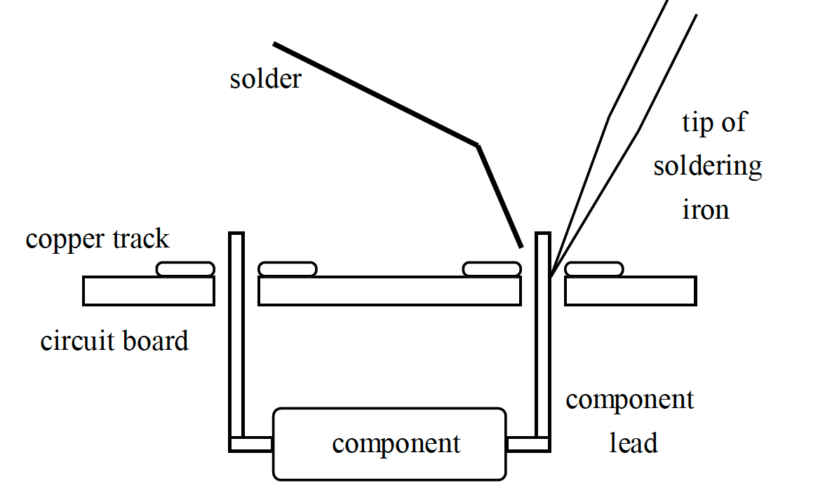
Referring to the illustration shown in Figure 19.1:
- Place the tip of soldering iron at the base of the joint to heat both the lead and the track.
- Touch solder to the base of the joint, preferably not on the iron The heat of the wire and track should melt the solder.
- When the solder runs like water, take the solder away FIRST.
- Take the iron away from the joint and allow it to cool.
- If all is well, a smooth curved joint is formed. Trim the wire using side cutters.
Hazards when soldering
The greatest danger is of burning oneself, either directly or as a result of touching heated metal which has not yet cooled down. A less obvious danger is from spots of molten solder, which might fall on skin or clothing. It is essential to use the safety equipment provided in the laboratory.
- Always return the soldering iron to the safety stand when not in use. NEVER place a soldering iron on the workbench where it will be a danger to yourself and others.
- Always place the workpiece on one of the heatproof mats, and ensure the extraction nozzle is positioned close by. This will ensure that the fumes are taken away from the workbench.
- Use eye protection in case spots of solder or surplus resin fly away from the It is essential to use safety glasses when cutting component leads since they can fly off at high speed.
- Ensure that the soldering iron does not come into contact with any mains cable, as the high temperature will melt plastic and expose conductors within a few seconds. The tool itself is earthed, so contact with a live wire should result in a blown fuse.
- Treat soldered joints with care, as metal parts can stay hot for several minutes after soldering.
- Report any accident to laboratory staff as soon as possible.
Demonstrations
Dr Davies has made three videos, accessible on Canvas (Video demonstration: Let’s build a Circuit Continuity Tester from a Tic Tac Box), in which he demonstrates the correct way of preparation and soldering the continuity tester.
You may wish to review these videos before performing the construction exercise. There is also a photograph through which Dr Davies has shown the stages in the assembly of his continuity tester. You are invited to check your work against these images.
Copyright © 2021-2024 Swansea University. All rights reserved.