Experiment 5: LCD Display Panel
Introduction
Experiment 5 introduces two new concepts. A new piece of hardware, the alphanumeric liquid crystal display, and a new software structure, the library.
Alphanumeric Display module
You will be given an Alphanumeric Display module. This module can display two lines of 16 characters, using any characters in the ASCII standard list plus several special characters and up to eight user-defined characters. The interface to the display module is straightforward. Characters are written directly to the display and appear at the cursor position. Command characters can be sent which set the mode of operation of the display and allow the cursor to be moved around.
Direct information on this module can be obtained from the Farnell website, part number 3759026. Displays of this type are all based on a complex integrated circuit produced by Hitachi, part number HD 44780.
One complication of using the alphanumeric display module is the small number of input-output pins on the Arduino Nano. A special mode of operation is employed, in which eight-bit data bytes are transferred as two, four-bit “nibbles”. A demonstration program that is available to you shows you how numeric values and character strings can be displayed.
A copy of the data sheet for the display and a list of ASCII characters] can be found on Canvas.
Pinout of the Alphanumeric Display module
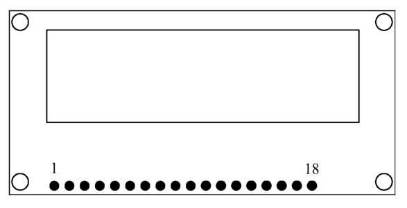
There are 18 pins arranged in a straight line, which allows the module to be plugged into a standard breadboard. The pins are grouped as eight for data, three for control, and three for power and contrast. A further four pins (pins 15 to 18) are used to illuminate the RGB “back light”. The functions of the pins are as follows:
Pin 1: Ground/Zero Volts
Pin 2: Supply positive, typically 5 V.
Pin 3: Contrast pin. Connected to a potentiometer to set the display contrast.
Pin 4: Register Select: an address line, selecting either command or data.
Pin 5: Read/Write: logic “0” for writes, logic “1” for reads.
Pin 6: Enable: writes a command or data to the display.
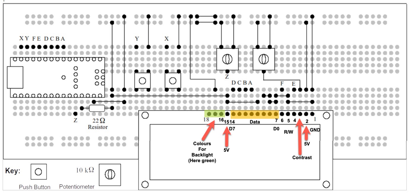
Pins 7 to 14: Data pins D0 to D7 respectively.
Pin 15: +5 V +5V connection for backlight.
Pins 16 to 18: zero volts for backlights red, green, blue respectively.
The 22\(\Omega\) resistor shown in the diagram is a safety feature designed to prevent damage to the Arduino nano should the potentiometers be wired-up incorrectly. It ensures that if the supply is shorted to ground by mistake, there will be insufficient current to damage the microcontroller or the display.
Once the sample program has been uploaded and the LCD panel is shown to be working, the resistor can be replaced by a wire link.
Library for LCD
Many devices such as the LCD require some complex software. A library, in this context, refers to additional code which is linked into the main program using “#include” and is accessed using specific commands. In this case, the LCD library is included as follows:
Some libraries, such as the SPI and IIC libraries, are present in the standard version of the Arduino IDE. Other libraries must be added using “Tools/Manage Libraries” from within the Arduino IDE.
Here are some examples of the extra commands that the library contains:
This command moves the cursor of the LCD to the start of the second line of the display.
In this case, the alphanumeric string, variables, or arithmetic expression contained within the brackets is printed at the current cursor position.
The best way to understand how the LCD hardware and software work, is to build the circuit that follows on plug-in breadboard and to try the example programin Listing 25.1.
Functions of the Demonstration Program
As explained previously, the LCD module is connected in “4-bit mode”, to minimise the number of connections to the Arduino Nano processor. In addition to the 4 data bits, there are two command signals, Register Select (RS) and Enable (E). These are the absolute minimum number of connections between the LCD and the processor. An additional command signal, Read/Write, (R/W) is connected permanently to logic “0”.
There are two potentiometers on the demonstration board. One sets the contrast of the LCD, which is necessary to adjust the correct balance between the illuminated and dark pixels. The other potentiometer sets the voltage on analogue input A7.
Two push buttons are provided, connected to digital inputs D10 and D11. Note the use of pinMode in setup(), which turns on the pull-up resistors associated with inputs D10 and D11.
Copy the text of the demonstration program into a new Arduino sketch, and compile and upload in the usual way. When the program is running, it should display the message “hello world!” on the first line. On the second line, the first few characters are a count in seconds since the board was reset. The remainder of the second line shows the message “ADC = xxxx”, where “xxxx” represents a number between 0 and 1023, as determined by the setting of the potentiometer. Pressing the push buttons should result in the characters “R” or “L” being displayed near the end of the first line of the display.
If the range of the ADC is for not to be in the range 0 to 1023 (it is typically limited to around 940), then replace the 22\(\Omega\) resistor by a wire link as noted earlier.
The example code provides examples of how to set the display and write messages and variables. The example code can form the basis of the exercise that follows.
Task for Experiment 5
The exercise for this experiment is to configure the demonstration board as a bar graph display, similar to the exercise in Experiment 3. But in this new exercise, the bar graph is not a line of LEDs, it is the top line of the LCD. There are 16 character positions, so that each “block” of the bar graph will correspond to 64 values from the ADC (which is 10 bits, so there are 1024 possible values).
Here is the required display. Retain the line “ADC =” followed by the ADC value displayed on the second line, this will be useful when testing your program.
and so on until:
The “#” character is only here as an example. A more suitable character is available on the LCD, which corresponds to ASCII code 255 and appears as a rectangle of 7 by 5 pixels. It can be printed as follows:
There are a number of ways to achieve this programme. One would be to “trap out” the zero value, and print a line of 16 space characters, then divide the ADC value by 64 and use this as an index in a character array.
An alternative would be to write a program loop which decrements the scaled ADC value and printing “#” until the result is zero.
Assessment of Experiment 5
As with previous exercises, the plug-in breadboard should be photographed with your student card and added to your laboratory diary. A listing of your program should be included, with plenty of comments. A program without comments is of only limited value, as nobody else can follow it!
Code Listing
LCD Panel Demonstration Program.
/*
  LiquidCrystal Library - Hello World

  Demonstrates the use a 16x2 LCD display.  The LiquidCrystal
  library works with all LCD displays that are compatible with the
  Hitachi HD44780 driver. There are many of them out there, and you
  can usually tell them by the 16-pin interface.

  This sketch prints "Hello World!" to the LCD
  and shows the time and the value of analogue input A7

  The circuit:
   LCD RS pin to digital pin 8
   LCD Enable pin to digital pin 9
   LCD D4 pin to digital pin 4
   LCD D5 pin to digital pin 5
   LCD D6 pin to digital pin 6
   LCD D7 pin to digital pin 7
   LCD R/W pin to ground
   LCD VSS pin to ground
   LCD VCC pin to 5V
   10K resistor:
   ends to +5V and ground
   wiper to LCD VO pin (pin 3)
   analogue input to Nano A7

  Library originally added 18 Apr 2008
  by David A. Mellis
  library modified 5 Jul 2009
  by Limor Fried (http://www.ladyada.net)
  example added 9 Jul 2009
  by Tom Igoe
  modified 22 Nov 2010
  by Tom Igoe
  modified 7 Nov 2016
  by Arturo Guadalupi
  this sketch modified 24th Nov 2021
  by Timothy Davies


*/

// include the library code:
#include <LiquidCrystal.h>

// initialize the library by associating any needed LCD interface pin
// with the arduino pin number it is connected to
const int rs = 8, en = 9, d4 = 4, d5 = 5, d6 = 6, d7 = 7;
LiquidCrystal lcd(rs, en, d4, d5, d6, d7);

// define the left and right push buttons
const int left = 11, right = 10;

void setup() {
  // set up the LCD's number of columns and rows:
  lcd.begin(16, 2);

// Print a message to the LCD.
  lcd.print("hello, world!");

  pinMode(left, INPUT_PULLUP);
  pinMode(right, INPUT_PULLUP);
}

void loop() {
  // set the cursor to column 0, line 1
  // (note: line 1 is the second row, since counting begins with 0):
  lcd.setCursor(0, 1);

// print the number of seconds since reset:
  lcd.print(millis() / 1000);

  //move the cursor to the middle of the second line
  lcd.setCursor(6, 1);

  //print the message with extra spaces to blank previous analogue data
  lcd.print("ADC =     ");

  //move the cursor to the printing position for the analogue data
  lcd.setCursor(12, 1);

  //print the value of analogue input A7 as 0 to 1023
  lcd.print(analogRead(7));

  if (digitalRead(left) == 0)
  {
    lcd.setCursor(14, 0);
    lcd.print("L");
  }
  else if (digitalRead(right) == 0)
  {
    lcd.setCursor(14, 0);
    lcd.print(" R");
  }
  else {
    lcd.setCursor(14, 0);
    lcd.print("  ");
  }
  delay(100);
}
View and download the code from GitHub gist lcd_panel.ino.
Wokwi simulation of program using the LCD panel
You can run a wokwi simulation of this circuit which was created by EEE project student Yousef Alsayegh (class of 2024-2025). The link is Lab 5: LCD Panel Demonstration Program and it uses the code from Listing 25.1. You can copy and edit this to create your own simulation of the assessed program.
If you do, it would be useful to provide links to the simulations in your lab diary.
Photograph of Prototype Board with LCD Panel Display
The following photograph (Figure 25.3) has been provided by Dr Davies who created this experiment.
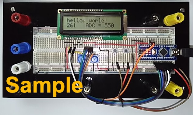
Copyright © 2021-2024 Swansea University. All rights reserved.