Experiment 1: Binary Counter
How can the microcontroller make something happen?
The microcontroller on the Nano board has a number of parallel ports, which can be used to make something happen in the world outside the plastic package. Parallel ports are usually groups of eight pins, however on the Arduino Nano not all the pins are brought out to the edge of the board. So, working within this constraint, Experiment 1 will begin with the construction and programming of a six-bit binary counter, which can count from zero to \(63\) (\(2^6 - 1\)).Parallel ports and data direction registers
In most microcontrollers, including the Atmel ATMega32 used in the Arduini Nano board, we set the digital port to be either an input or an output by setting a value in a special register, associated with the parallel port, which is called the Data Direction Register (DDR).
The DDR settings that provide the six outputs that we need for this experiment are shown in Table 21.1.
| DDRC7 | DDRC6 | DDRC5 | DDRC4 | DDRC3 | DDRC2 | DDRC1 | DDRC0 |
|---|---|---|---|---|---|---|---|
| 0 | 0 | 1 | 1 | 1 | 1 | 1 | 1 0 |
There are two ways of setting the bits in the DDR. Individual bits can be set using an Arduino specific command, pinMode. For this experiment, we shall write directly to the DDR corresponding to Port C, which is designated DDRC in our programme. In the example shown above, the top two bits of Port C will be inputs (DDRC7=0, DDRC6 = 0) and all the remaining bits will be outputs. This is a more general way of setting a DDR in different versions of embedded “C”.
Writing a number to the port register itself will cause a binary pattern to appear on the corresponding pins of the designated port, according to their binary weights. For example, bit 0 has a binary weight of \(2^0 = 1\), bit 1 has a binary weight of \(2^1 = 2\), bit 2 has a binary weight of \(2^2 = 4\), all the way up to bit 7 which has a binary weight of \(2^7 = 128\).
Method
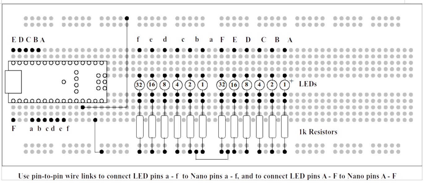
Construct the circuit shown in Figure 21.1 using the components supplied in your laboratory kit:
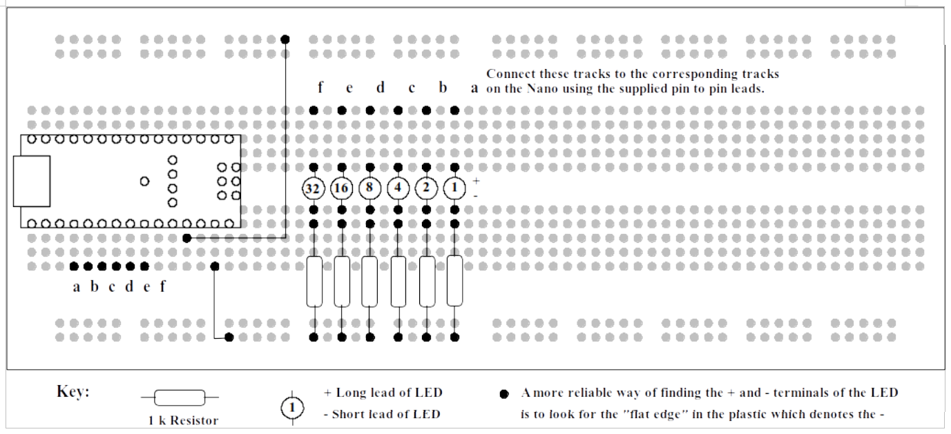
Counter circuit.
Our First Programme
Now you are familiar with the Arduino IDE from running “Blink” in section on the blink, the next step is to write a new programme.
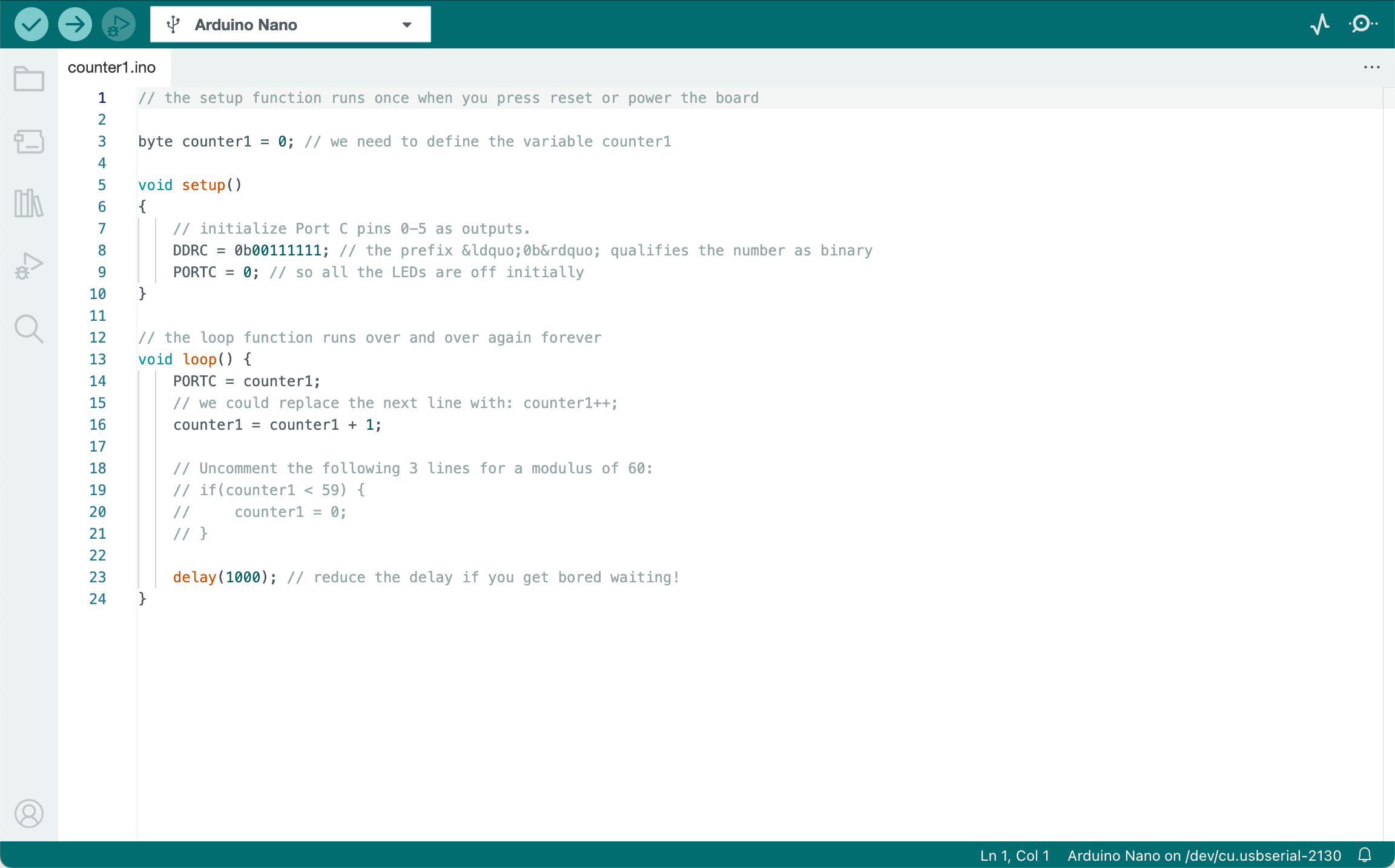
Listing 21.1 shows the text of a program which will illuminate the LEDs in a binary sequence, starting from zero (all LEDs off) to 63 (all LEDs on). Then the LEDs will go back to zero. The time it takes to count is controlled by a “time wasting” delay, using the Arduino specific command delay().
First connect your Arduino Nano board to your PC with the cable provided. Next open Arduino IDE 2 and select the connection and board as described in section initial set up. From the file menu select “New Sketch”. Click on the small clipboard icon at the top-right corner of the code listing Listing 21.1 ( ) to copy the code and paste it into the code window of the new sketch. Save the sketch file as
 counter1.
THE Arduio IDE will close then reopen with the code for a new Sketch project called counter1.ino loaded in the code editor as shown in Figure 21.1.
Now that the file has been entered into the computer and an Arduino sketch project it must be converted into a form the Arduino board can accept. This operation is called compilation.
Click on the icon which starts the compilation. This is the blue tick near the top of the window, also called Verify. After a few seconds, the display area at the bottom of the window should say “compilation complete”. If it does not, and some error message appears, check carefully that the program has been entered correctly and try again.
When the program has been compiled successfully, it must be uploaded to the Arduino. Click on the blue arrow near the top of the window, called Upload. This operation should only take a few seconds. The message “Done uploading” tells us that the upload operation has been successful, and the LEDs should start counting.
If the upload fails, there are a number of things to check. Under “tools”, there are a number of settings, e.g.
- Board type:
Arduino Nano - Processor:
ATmega328P - Port:
/dev/ttyUSB0(for example only; this will differ for PC and Mac)
If the above are wrong, then the upload will fail. Ask a demonstrator for help!
Lets make a decision
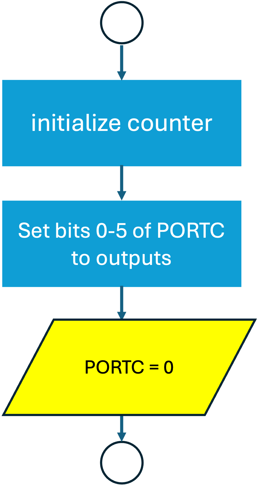
The flow-charts for Listing 21.1 is given in Figure 21.2 and Figure 21.3. Note that the codes are similar to the flow-charts given in Getting Started. There are just a couple of steps in the setup sub-process and one less output task in the loop. Note also that we have used english statements rather than code in the block labels.
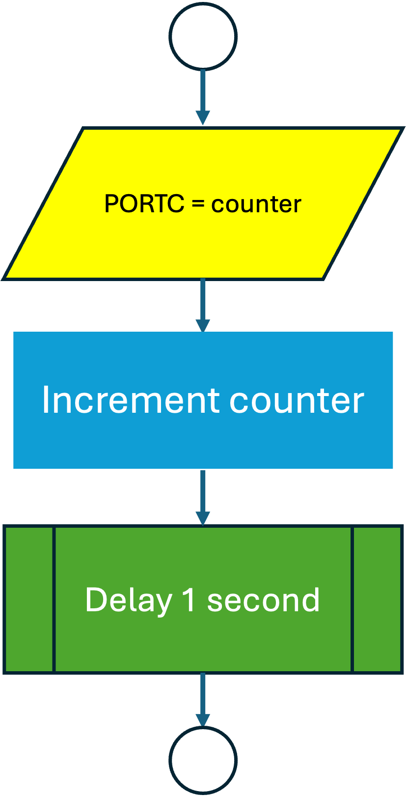
The example program counts from zero to 255 and then back to zero, though we see the LEDs being illuminated from zero to 63 as there are only six LEDs. The counts from 64 to 127 look just the same as zero to 63! As the counter is only 8 bits, when we get to 255, the counter is reset to 0. This behaviour is not obvious from the flow-chart for the loop subprocess.
Supposing we need a counter that counts from zero to 59, and then back to zero. This is often required, for example in time-keeping programmes (60 seconds in a minute, 60 seconds in an hour). The number of count values (60 in this case) is called a Modulus.
There are several ways we can add a modulus to our counter programme. Here we will use a decision.
If we add a decision block to the flow chart for the loop, as shown in Figure 21.4, we can control the maximum count that can occur.
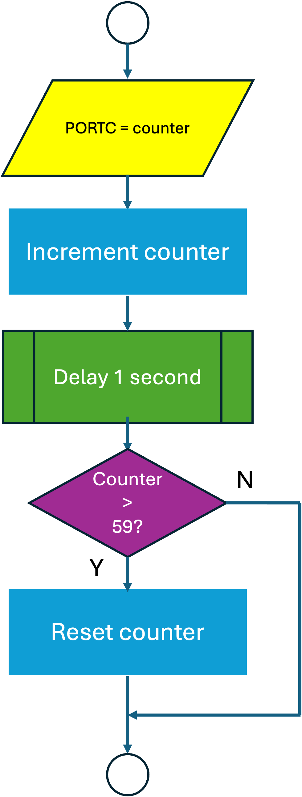
The code that corresponds to the decision block in Figure 21.4 is
In this code, we have made a decision! If the value of the variable counter is increased beyond 59, then it will be set back to zero, so the LEDs never advance beyond 59.
Why bother with counts greater than 60? Well, if the program is not properly initialised then there will be a number of false counts.
If you are not familiar with “C” programming, then you will notice that there are two kinds of “equals” in the extra line. The “greater than” (>) is a comparison and does not change any values. In other words the value of the variable counter is compared with the fixed value of 59. If the condition is true, then the contents of the “braces” (squiggly brackets) are executed. The single equals (=) is an assignment and forces the value of the variable to the fixed value zero.
Just to make life more interesting, in “C” there is a “double equals” ==). This can be a source of confusion when starting to program in the “C” language. It is used to compare two numbers, for example as follows:
There are lots of “C” commands which reduce the amount of text that you have to write. For example, instead of adding 1 to the variable counter1 we can use the increment operator (++) to increment a variable by 1:
This has the same effect as adding “1” to the variable counter and reassigning the new value to counter which is what:
does.
Lets do it again!
Now that we are masters of the modulus counter, lets repeat the operation by connecting another set of LEDs to port B, and adding extra lines to the program as shown in Listing 21.2.
This will require another variable, for example “counter2”.
In addition, let us increment counter1 when counter2 overflows, (changes from 59 to zero) so that one set of LEDs is counting in seconds and the other set of LEDs is counting in minutes.
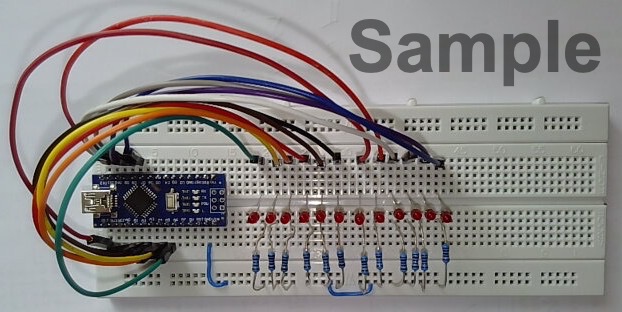
Add another set of six LEDs and resistors to the Breadboard as shown in Figure 21.5.
Modify the program to include the extra lines and compile then upload. If this is successful, then the LEDs on port B will count as far as 59 (0b0111011) and then all go out and start counting again. At the instant the LEDs on port B go out, the LEDs on port C will advance by one. So, if we have the patience, after an hour the LEDs will reach their maximum value of 59 minutes, 59 seconds (0b0111011 0b0111011) and all go out. Then the counter starts counting again from all zeros.
Let’s do it differently
So far we have used simple arithmetic operations such as addition to increment the variables, then compare with a fixed modulus. An alternative is to use a for(;;) loop.
Let’s look at the elements of a for(;;) loop:
for (variable = initial value; condition to be met; operation on variable) {
   code to be executed in for loop;
}
A better way of understanding the for(;;) loop is to look at a practical example;
In just three lines of code, the start and end values of the loop are set up, and the increment defined, followed by the code to be executed each time around the loop. This illustrates the compact nature of the “C” language.
This for(;;) loop only executes once, so we still need to make it repeat, which is made possible by the loop function in the Arduino program. Suppose we embed this for(;;) loop in an outer for(;;) loop, which increments a different variable and writes to a different port? Then we will have achieved the same result as the program in Listing 21.2, but in a more elegant fashion:
for (counter1 = 0; counter1 < 60; counter1++) {
PORTC = counter1;
for (counter2 = 0; counter2 < 60; counter2++) {
PORTB = counter2;
delay(1000)
}
}The “heart” of the program is just a few lines of code!
Modify the program as shown in Listing 21.3, compile and upload, and check that it really does what we expect. You may find it convenient to reduce the delay from 1000 to speed up the operation of the counters.
Assessment of Experiment 1
Open the document you are using as a laboratory diary and add a new section “Experiment 1”.
Create a flow-chart of the cascaded counter from the code given in Listing 21.2.
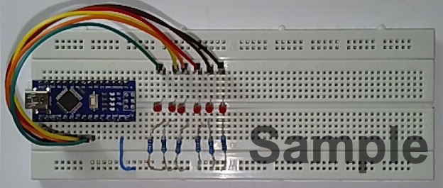
Take a photograph of the completed breadboard, with the twelve LEDs and resistors fitted. Include in your photo some means of identification, such as your student card.
When you have finished modifying the program to correspond with Listing 21.3, add some comments (preceded by the double oblique stroke “//”) and copy the text from the Arduino IDE and paste it into your laboratory diary as a code listing.
Redraw the flow chart to reflect the order of operation of the for loops. Hint: A flow chart for a nested for-loop like the one used in Listing 21.3 is given in Figure 5.10. Comment on any differences in flow-charts between that for Listing 21.2 and that for Listing 21.3.
We shall be expecting the flow-charts and code comments to demonstrate your understanding of the way the nested for(;;) loop works.
Why are comments so important? If someone else reads the program, the comments aid understanding. Also, if you return to working on a program after a couple of weeks, it is much easier to pick up where you left off.
A program without comments is incomplete!
Don’t forget to add to your lab diary entry some discussion of the results and a reflection on the outcomes of this first experimeent.
Lab 1 cannot be signed off unless the lab diary contains the two flow-charts for Listing 21.2 and Listing 21.2, the code listing for Listing 21.3 with added comments, and a photograph of the completed modular-60 counter.
Discussion, conclusions and reflection are not needed for the experiment sign-off but are required for the final lab-diary submission.
Code Listings
Basic counter
// Declare variable to be used as a counter.
// This has to be done outside `setup` and `loop` so that `counter` is visible
// inside both functions
byte counter;
// The setup function runs once when you press reset or power the board
void setup() {
// initialize counter
counter = 0;
// Set pins 0-5 of Port C as outputs.
DDRC = 0b00111111; // the prefix “0b” qualifies the number as binary
PORTC = 0; // so all the LEDs are off initially
}
// The loop function runs repeatedly forever
void loop() {
PORTC = counter;
// increment counter
// we could replace the next line with: counter1++;
// or the previous line with PORTC = counter1++;
counter = counter + 1;
// Uncomment the following three lines for a modulus of 60:
// if (counter > 59) {
// counter = 0;
// }
delay(1000); // reduce the delay if you get bored waiting!
}View and download the code from GitHub gist counter.ino.
Wokwi simulation of basic counter
You can run a wokwi simulation of this circuit which was created by EEE project student Yousef Alsayegh (class of 2024-2025). The link is Lab 1: Basic counter. You can extend the circuit by adding 6 further LEDs connected as in Figure 21.5 and use Listing 21.2 to implement the cascased modulo 60 counter. You can then paste your commented version of Listing 21.3 into the simulator’s code window to simulate final example.
If you succeed, it would be useful to provide links to the simulations in your lab diary.
Cascaded counter
// Declare variables to be used as counters.
byte counter1, counter2;
// the setup function runs once when you press reset or power the board
void setup() {
// define counters
counter1 = 0; counter2 = 0; // initialize counters
// initialize Ports B and C pins 0-5 as outputs.
DDRB = 0b00111111; DDRC = 0b00111111;
PORTB = 0; PORTC = 0; // both ports start from zero
}
// the loop function runs repeatedly forever
void loop() {
PORTB = counter2; // counter2 is our "seconds" counter
PORTC = counter1; // counter1 is our "minutes" counter
counter2++; // using the tip we learnt earlier
if (counter2 > 59) {
counter2 = 0;
counter1++;
if (counter1 > 59) {
counter1 = 0;
}
}
delay(1000); // again, reduce this delay if necessary to speed things up.
}View and download the code from GitHub gist counter2.ino.
Counter using for loop
// declare counters
byte counter1, counter2;
// the setup function runs once when you press reset or power the board
void setup() {
// initialize counters
counter1 = 0; counter2 = 0;
// initialize Ports B and C pins 0-5 as outputs.
DDRB = 0b00111111; DDRC = 0b00111111;
PORTB = 0; PORTC = 0; // both ports start from zero
}
// the loop function runs repeatedly forever
void loop() {
for (counter1 = 0; counter1 < 60; counter1++) {
PORTC = counter1;
for (counter2 = 0; counter2 < 60; counter2++) {
  PORTB = counter2;
  delay(1000);
}
}
}View and download the code from GitHub gist counter3.ino.
Photographs of Plug-in Breadboard
The following photographs (Figure 21.6 and Figure 21.7) were provided by Dr Davies who created this experiment.
Copyright © 2021-2024 Swansea University. All rights reserved.