Ultrasonic Range Finder
Brief: to connect an SR04 ultrasonic module to the Arduino Nano and the 16 by 2 LCD.
More information to get you started on this project is provided below.
The minimum requirement will be for the display to show a number which is proportional to the distance to the target. Additional marks will be given if the display is properly calibrated, can be switched from mm to feet and inches, and uses averaging to give a steady reading.
Marks will be awarded as follows:
0 to 40%: For a non-functional unit which nevertheless has some meaningful reading.
40 to 50%: For a minimal implementation of the specification, with a reading which goes up and down as the target is moved away from and towards the sensor.
50 to 60%: For a range finder with accurate calibration and averaging.
60 to 70%: For additional functionality such as a button to zero the reading for difference.
70% plus: A range finder with advanced functionality such as area measurement.
Technical Information
Here are some thoughts about the ultrasonic range finder, and a brief piece of code which is FAR from ideal!
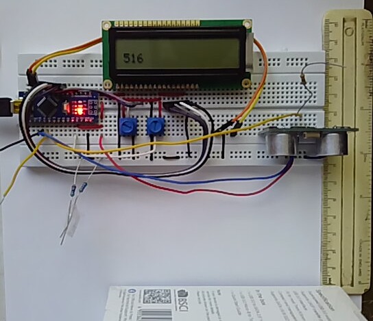
Here is a picture of the Experiment 5 breadboard with the ultrasonic module connected, and showing a time interval of about 500μs for the echo. That corresponds to about 160 mm, divided by two for out and back, which is 80 mm. Look at the ruler; the distance from the cardboard box and the back of the sensor is about 80 mm, so we are not far off the correct measurement.

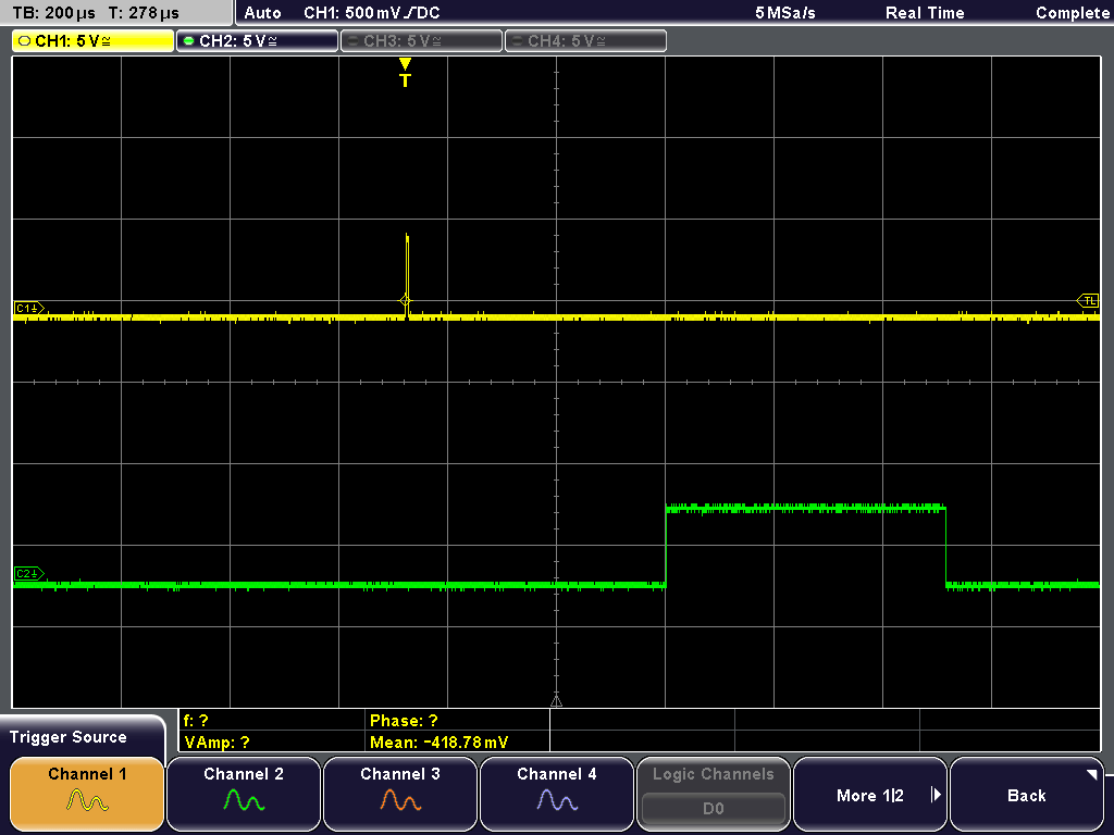
Now look at the waveforms on the oscilloscope.

You will see that the “trig” pulse is very narrow, about 5 μs, which is plenty. The echo pulse is about 500 μs, corresponding to the number on the LCD.
The code to produce the above waveform follows. It is for GUIDANCE ONLY, as it has no averaging or scaling, and it “locks up” if no echo is received.
Trig is on A0/digital pin 14, and Echo is on A1/digital pin 15.
/*
  LiquidCrystal Library - Hello World

 Demonstrates the use a 16x2 LCD display.  The LiquidCrystal
 library works with all LCD displays that are compatible with the
 Hitachi HD44780 driver. There are many of them out there, and you
 can usually tell them by the 16-pin interface.

 This sketch prints "Hello World!" to the LCD
 and shows the time and the value of analogue input A7

  The circuit:
 * LCD RS pin to digital pin 8
 * LCD Enable pin to digital pin 9
 * LCD D4 pin to digital pin 4
 * LCD D5 pin to digital pin 5
 * LCD D6 pin to digital pin 6
 * LCD D7 pin to digital pin 7
 * LCD R/W pin to ground
 * LCD VSS pin to ground
 * LCD VCC pin to 5V
 * 10K resistor:
 * ends to +5V and ground
 * wiper to LCD VO pin (pin 3)
 * analogue input to Nano A7

 Library originally added 18 Apr 2008
 by David A. Mellis
 library modified 5 Jul 2009
 by Limor Fried (http://www.ladyada.net)
 example added 9 Jul 2009
 by Tom Igoe
 modified 22 Nov 2010
 by Tom Igoe
 modified 7 Nov 2016
 by Arturo Guadalupi
 this sketch modified 24th Nov 2021
 by Timothy Davies


*/

// include the library code:
#include <LiquidCrystal.h>

#define trig 14
#define echo 15

// initialize the library by associating any needed LCD interface pin
// with the arduino pin number it is connected to
const int rs = 8, en = 9, d4 = 4, d5 = 5, d6 = 6, d7 = 7;
LiquidCrystal lcd(rs, en, d4, d5, d6, d7);

// define the left and right push buttons
const int left = 11, right = 10;


unsigned int starttime=0; // 0 - 65,355
unsigned int stoptime=0;
unsigned int distance=0;


void setup()
{
  // set up the LCD's number of columns and rows:
  lcd.begin(16, 2);

  pinMode (trig,OUTPUT);

}

void loop()
{
  // set the cursor to column 0, line 1
  // (note: line 1 is the second row, since counting begins with 0):
  lcd.setCursor(0, 1);

  digitalWrite(trig,1); //send out the trig pulse
  digitalWrite(trig,0);

  while (digitalRead(echo)==0) {}  //wait for echo to go high

  starttime = micros();

  while (digitalRead(echo)!=0) {} wait for echo to go low again

  stoptime = micros();

  distance = stoptime-starttime;
  lcd.print("         "); //blank previous result
  lcd.setCursor(0, 1);
  lcd.print(distance);

  delay (100);
}
View and download the code from GitHub gist range_finder.ino.
Copyright © 2021-2024 Swansea University. All rights reserved.