For this exercise you are provided sample keyboard interrupt programs in both C and Assembly in the appendices; make sure that you have downloaded electronic versions of the program from the GitHub repository before the exercise. The program uses the interrupt generated by push buttons to switch on/off the LEDs on the MC9S08AW60 evaluation board.
You are to carry out the following three tasks with this exercise:
- Use the sample program to practice using interrupt mechanism to interface peripheral devices with the evaluation board.
- Answer the questions related to the CPU interrupt procedure (4 marks).
- Adjust the sample program to use the onboard switches to control the display of your student number (6 marks).
You can view this document as a web page HTML, PDF or as a Word Document .docx.
I. Experiment with the Sample Program
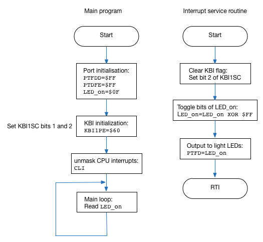
The sample program, “kbi_interrupt.c” and “kbi_interrupt.asm”, flashes onboard LEDs upon the interrupt requests generated by the keyboard inputs, which are SW3 and SW4 used as keyboard inputs 6 and 5, respectively. The flowchart of the program is shown in Figure 1. Enter it or copy the electronic file onto your CodeWarrior project, which is created targeting on HCS08 CPU family and MC9S08AW60 MCU.
After you create your own keyboard interrupt project, you can use the evaluation board to debug the sample keyboard interrupt program. Next we will introduce how to use the evaluation board to configure peripheral device inputs and generate interrupts.
A. Interrupt Generation with the Evaluation Board
The evaluation board includes four pushbutton switches (SW1-SW4) which can provide momentary active low input for user applications. SW3 and SW4 are connected to MCU Port PTD3 and PTD2 respectively. If the pins of PTD3 and PTD2 are configured as KBI inputs, they will be read with “1” if the corresponding pushbutton is not pressed and “0” if pressed. Edge events and edge/level events can be easily generated by pressing SW3 and SW4. The KBI inputs can detect the selected events as configured by the programmer and generate interrupt requests if the keyboard interrupt for the inputs is enabled.
B. Experiment with the Interrupt Mechanism
Once we know how to generate keyboard interrupt events, we can use the sample program and evaluation board kits to experiment with interrupt mechanism.
According to the interrupt procedure, CPU will leave the main program and run the interrupt service routine (ISR) if interrupt for the keyboard module is enabled. You can use “Single-step” or set breakpoint(s) to observe how the CPU responds to interrupt requests. After the CPU finishes the ISR, it returns to the main program. You can generate as many keyboard-interrupts as you like by pushing down the switches.
You can also experiment with the detection of a rising edge and rising edge/high level events and correspondingly generating keyboard interrupt events by configuring the keyboard interrupt status and control register.
II. Questions
By doing experiments with the slightly modified sample C programme, you are required to answer the following questions.
Upon the generation of keyboard interrupt requests, the ISR will be run by the CPU. Experiment with the evaluation board, record and compare the content in the stack just before and after the CPU enters the ISR and just before and after the CPU leaves the ISR corresponding to a keyboard interrupt. You can get the stack pointer value from the register panel in the real-time debugger window.
Explain why the stack content changes as you have observed.
Make a careful note of your observations as you will need them for the assessment later.
III. Adjust the Sample Program to Display your Student Numbers
All the eight KBI inputs share the KBI source. In this task you are required to adjust the ISR shown in the Appendix, in order to determine which of the two pushbuttons SW3 and SW4 triggered a KBI interrupt and correspondingly display a student number of a member in your team.
Suppose the student numbers for your team are 43210 and 12345, respectively. On reset, if the pushbutton SW3 is pressed down, in your ISR you should light up the leftmost nonzero digit 4 in the first student number over LEDs (i.e., in a binary format using four LEDs). Then the CPU should leave the ISR and return to the main program. If SW3 is released and then pressed down again, the next digit 3 in the first student should be displayed over LED in your ISR. With more pressing of SW3, the following digits in the first student number are displayed sequentially. Note that after the rightmost digit 0 was displayed over LEDs upon the last pressing of SW3, the leftmost digit 4 will be displayed over LEDs upon new SW3 pressing. Similar operations are performed for the second student number 12345 if the pushbutton SW4 is pressed.
You are required to design and debug the ISR program (using the C language), and submit the completed program as a single file named kbi_SN.c (where SN is your student number). The assessment point on Canvas LMS is called Assessment of Microntrollers Laboratory Exercise 1.
Appendix A
Sample Program in C
/* kbi_interrupt.c */

#include <hidef.h>	 /* for EnableInterrupts macro */
#include "derivative.h"	/* include peripheral declarations */
#define VNkeyboard 22   /* Interrupt vector for Keyboard */

typedef unsigned char muint8;
typedef unsigned short muint16;
typedef unsigned long muint32;

typedef char mint8;
typedef short mint16;
typedef long mint32;

muint8 LED_onseq;

void main(void)
{

	SOPT = 0x00;		/* disable COP */

	/* begin LED/switch test */

	PTDPE = 0xFF;		/* enable port D pullups for push button switch interrupt */

	/* Init_GPIO init code */
	PTFDD = 0xFF;		/* set port F as outputs for LED operation */
	LED_onseq = 0x0F;	/* initialize LED_onseq */

	//*********************************************************************************
	//* KBI1PE7 * KBI1PE6 * KBI1PE5 * KBI1PE4 * KBI1PE3 * KBI1PE2 * KBI1PE1 * KBI1PE0 *
	//*********************************************************************************
	// KBI1PE register; each bit selects the corresponding keyboard interrupt pin.

	//*********************************************************************************
	//* KBEDG7  * KBEDG6  * KBEDG5  * KBEDG4  *   KBF   *  KBACK  *  KBIE   *  KBIMOD *
	//*********************************************************************************
	// KBI1SC register; top four bits 0 = falling edge 1 = rising edge of corresponding
	// pins KBEDG7 to 4. KBF keyboard interrupt flag, KBACK acknowledges interrupt flag.
	// KBIE turns on the keyboard interrupt system, KBIMOD 0 = edge detection.

	KBI1SC_KBIE = 0;	//Make sure interrupt is OFF
	KBI1PE = 0b01100000;	//Turn on interrupts for pins 5 and 6 only
	KBI1SC_KBIMOD = 0;	//Make sure we are on edge operation
	KBI1SC_KBACK = 1;	//Clear any possible pending interrupts
	KBI1SC_KBIE = 1;	//Turn on selected keyboard interrupts

	EnableInterrupts;	// enable interrupts globally ("big switch")

	for(;;)
	{

	}	/* loop forever */
		/* make sure that you never leave main! */
}

// What follows is the interrupt service routine, which is called if either of the
// selected keyboard interrupts occurs on pins 5 and 6. However, Port D is tested
// and the LED toggle only happens if SW3 is pressed. (KBI 6, Port D3).

interrupt VNkeyboard void intKBI_SW()
{
	KBI1SC_KBACK = 1;		// acknowledge interrupt
	// this is the business of the interrupt
	if (PTDD_PTDD3 == 0)
	{
		PTFD = LED_onseq;
		LED_onseq ^= 0xFF;	// toggle LED_onseq bits
	}
	// do nothing if not keyboard interrupt VNkeyboard
}
View on GitHub
Appendix B
Sample Program in Assembly
;*************************************************************************
;*	kbi_adc.asm                                                      *
;*                                                                       *
;*	MC9S08AW60 Evaluation board keyboard interrupt example           *
;*	- Switch SW3 onboard connected to Port D bit 3, KBI pin6;        *
;*	- Switch SW4 onboard connected to Port D bit 2, KBI pin5         *
;*                                                                       *
<<<<<<< HEAD
;*	Function:                                                        *
;*	On reset, all LEDs are off. When either SW3 or SW4 are pressed,  *
;*	then the ADC channel 8 is read and sent to the LEDs.             *
=======
;*	Function:                                                            *
;*	on reset all LEDs will light on. If SW3 or SW4 pressed,              *
;*	an interrupt is generated, which set LEDs 0:3 to light on.           *
;*	More interrupts are generated if SW3 or SW4 are pressed.            *
>>>>>>> master
;*************************************************************************

		INCLUDE	'derivative.inc' ; Include derivative-specific definitions

FLASH		EQU		$2000
RAM		    EQU		$0070
WATCH		EQU		$1802

ConvComp	EQU		%10000000	;Mask for Conversion Complete flag

		ORG		RAM
LED_on		DS.B		1		; Define a variable VAR_D with a size of 1 byte

;Start program after reset

		ORG		FLASH
START_UP
		LDA		#$00
		STA		WATCH		; Turn off the watchdog timer

;Init_GPIO init code
		LDA     	#$FF
		STA     	PTFDD
		MOV    		#$0F, LED_on	; Initialize VAR_D, used to control the LEDs
		LDA     	#$FF
		STA    		PTDPE           ; Port D is enabled with pull-up
		RSP				; Reset stack pointer to $0080

;Enable interrupt for Keyboard input
		LDA     	#$60
		STA     	KBI1PE           ; KBI1PE: enable KBI function for pins 5 and 6 only
		BSET    	$02, KBI1SC      ; KBI1SC: KBACK=1, to clear KBI flag
		BSET    	$01, KBI1SC      ; KBI1SC: KBIE=1, enable KBI

		CLI                      	; Enable interrupt

MAINLOOP
		LDA     	LED_on           ; Simple loop with "dummy" operation
		BRA		    MAINLOOP

;Interrupt service routine for a keyboard interrupt generated upon the press of a pushbutton
;with a falling edge (transition from high logic level "1" to low logic level "0")
LED_SWITCH
		BSET    	$02, KBI1SC     ; Clear KBI flag
		LDA     	#8		; Select analogue input 8 (the blue potentiometer).
		STA     	ADC1SC1         ; ADC conversion will start after a number is written to ADC1SC1 register.
ADCLOOP
		LDA     	ADC1SC1         ;
		AND		    #ConvComp	    ; Check the COCO bit (conversion complete flag).
		BEQ     	ADCLOOP         ; if not complete, wait in the ADC loop.
		LDA     	ADC1RL          ; if complete, read the ADC outcome (digital value) from the register.
		STA     	PTFD            ; display over LED bar
		RTI

;INT_VECTOR
		ORG     	$FFD2
		DC.W    	LED_SWITCH

		ORG    		$FFFE
		DC.W    	START_UP
View on GitHub

EG-252 Resources by Swansea University is licensed under a Creative Commons Attribution-ShareAlike 4.0 International License.