Using Laplace Transforms for Circuit Analysis
First Hour's Agenda
We look at applications of the Laplace Transform for
- Circuit transformation from Time to Complex Frequency
- Complex impedance
- Complex admittance
Circuit Transformation from Time to Complex Frequency
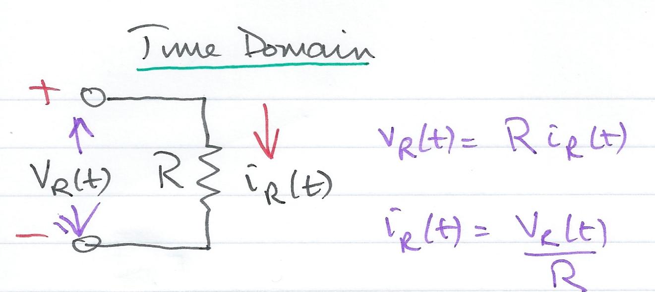
Resistive Network - Time Domain
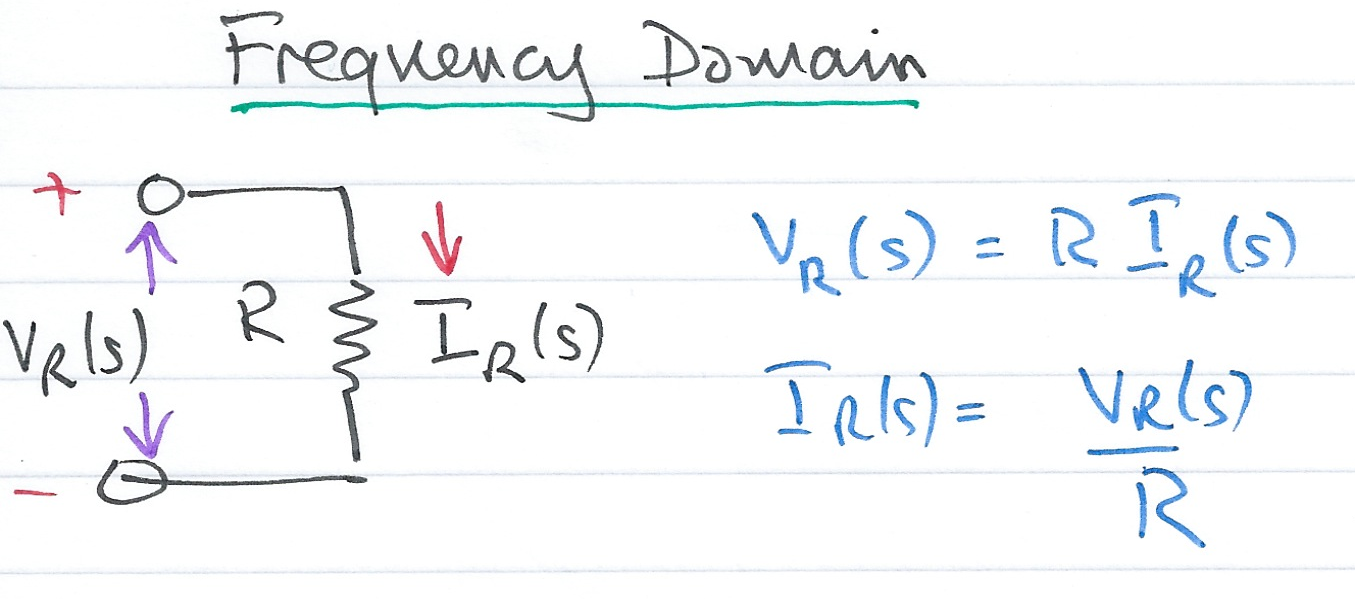
Resistive Network - Complex Frequency Domain
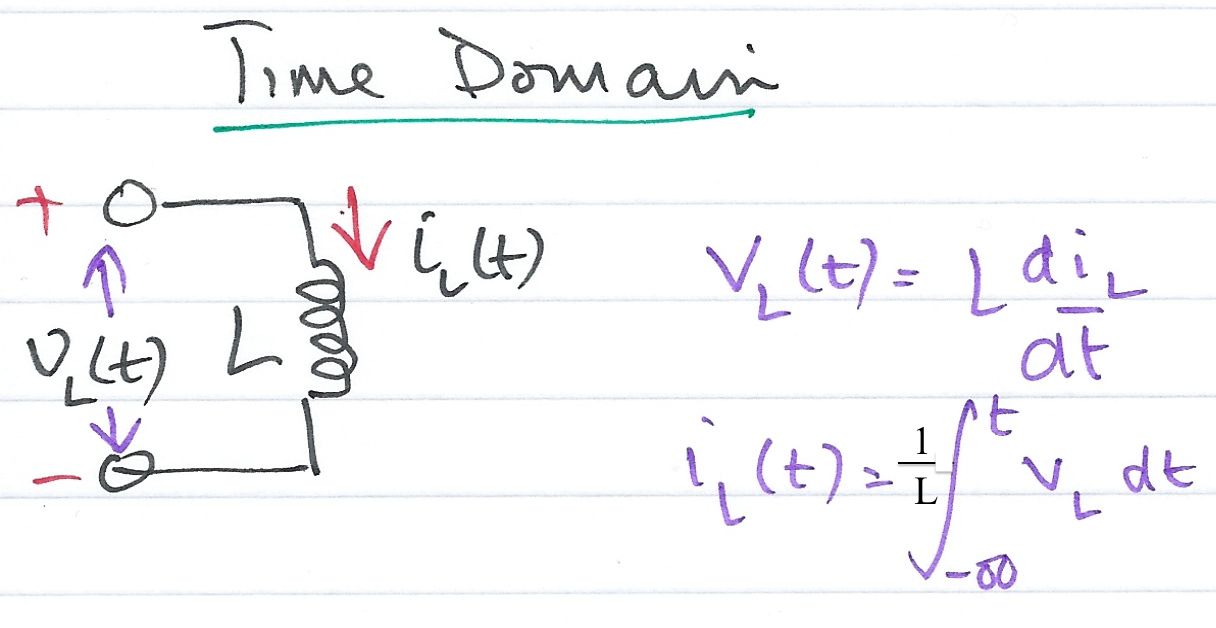
Inductive Network - Time Domain
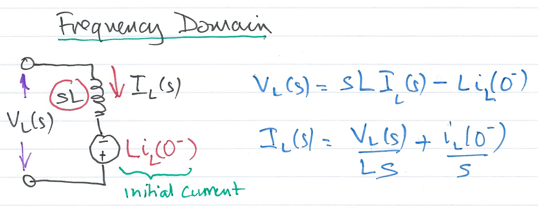
Inductive Network - Complex Frequency Domain
Capacitive Network - Time Domain
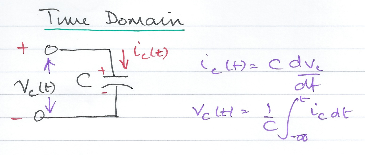
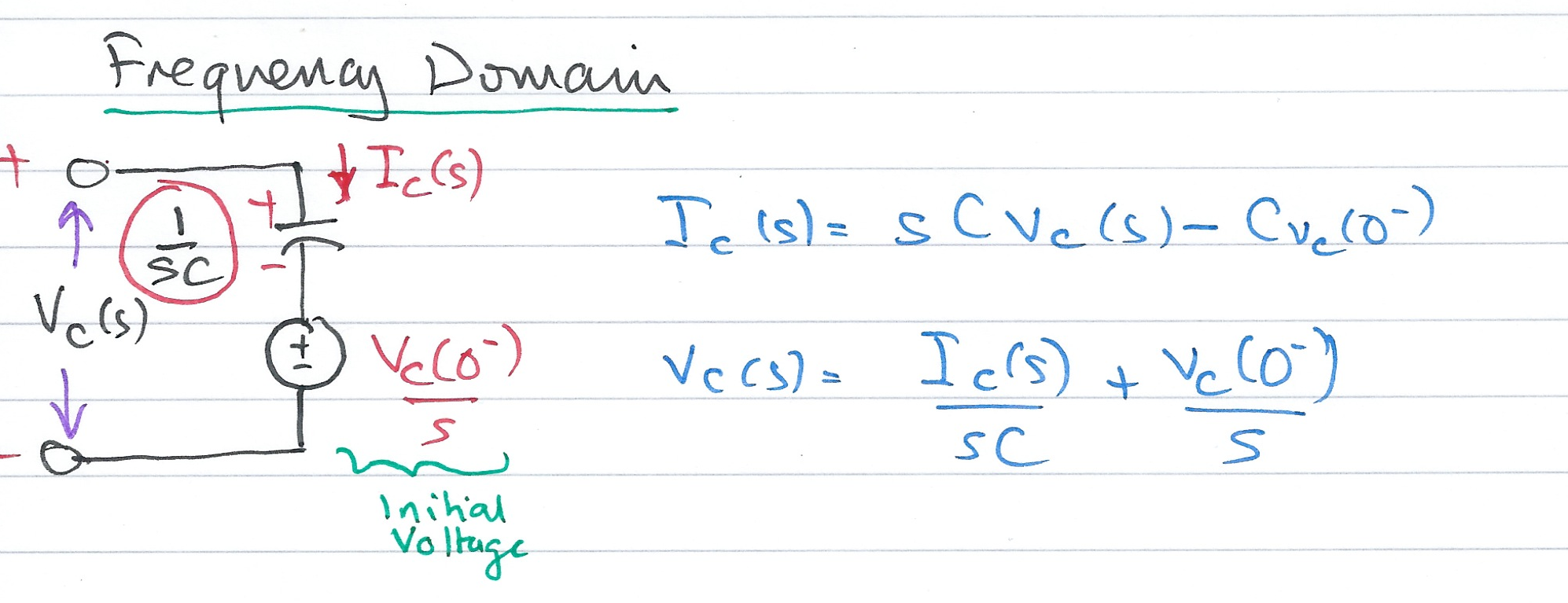
Capacitive Network - Complex Frequency Domain
Examples
Example 1
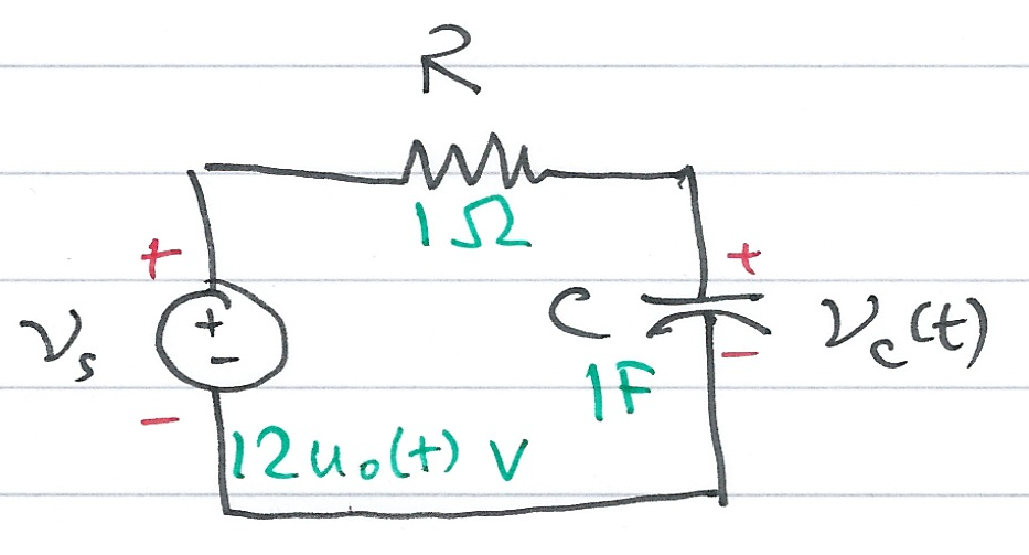
Use the Laplace transform method and apply Kirchoff's Current Law (KCL) to find the voltage $v_c(t)$ across the capacitor for the circuit below given that $v_c(0^-) = 6$ V.
Example 2
Use the Laplace transform method and apply Kirchoff's Voltage Law (KVL) to find the voltage $v_c(t)$ across the capacitor for the circuit below given that $v_c(0^-) = 6$ V.

Example 3
In the circuit below, switch $S_1$ closes at $t=0$, while at the same time, switch $S_2$ opens. Use the Laplace transform method to find $v_{\mathrm{out}}(t)$ for $t > 0$.

Show with the assistance of MATLAB (See solution3.m) that the solution is
$$V_{\mathrm{out}}=\left(1.36e^{-6.57t}+0.64e^{-0.715t}\cos 0.316t - 1.84e^{-0.715t}\sin 0.316t\right)u_0(t)$$
and plot the result.
Solution to Example 3
We will use a combination of pen-and-paper and MATLAB to solve this.
1. Equivalent Circuit
Draw equivalent circuit at $t=0$
2. Transform model
Convert to transforms
3. Determine equation
Determine equation for $V_{\rm out}(s)$.
4. Complete solution in MATLAB
In the lecture we showed that after simplification for Example 3
$$V_{\mathrm{out}}=\frac{2s(s+3)}{s^3 + 8s^2 + 10s + 4}$$
We will use MATLAB to factorize the denominator $D(s)$ of the equation into a linear and a quadratic factor.
Find roots of Denominator D(s)
r = roots([1, 8, 10, 4])
r =

  -6.5708 + 0.0000i
  -0.7146 + 0.3132i
  -0.7146 - 0.3132i
Find quadratic form
syms s t
y = expand((s - r(2))*(s - r(3)))
y =

s^2 + (804595903579775*s)/562949953421312 + 3086772113315577969665007046981/5070602400912917605986812821504
Simplify coefficients of s
y = sym2poly(y)
y =

    1.0000    1.4292    0.6088
Complete the Square
Plot result
t=0:0.01:10;
Vout = 1.36.*exp(r(1).*t)+0.64.*exp(real(r(2)).*t).*cos(imag(r(2)).*t)-1.84.*exp(real(r(3)).*t).*sin(-imag(r(3)).*t);
plot(t, Vout); grid
title('Plot of Vout(t) for the circuit of Example 3')
ylabel('Vout(t) V'),xlabel('Time t s')
Alternative solution using transfer functions
Vout = tf(2*conv([1, 0],[1, 3]),[1, 8, 10, 4])
Vout =

       2 s^2 + 6 s
  ----------------------
  s^3 + 8 s^2 + 10 s + 4

Continuous-time transfer function.
impulse(Vout)
Complex Impedance Z(s)
Consider the $s$-domain RLC series circuit, wehere the initial conditions are assumed to be zero.

For this circuit, the sum
$$R + sL + \frac{1}{sC}$$
represents that total opposition to current flow. Then,
$$I(s) = \frac{V_s(s)}{R + sL + 1/(sC)}$$
and defining the ratio $V_s(s)/I(s)$ as $Z(s)$, we obtain
$$Z(s) = \frac{V_s(s)}{I(s)} = R + sL + \frac{1}{sC}$$
The $s$-domain current $I(s)$ can be found from
$$I(s) = \frac{V_s(s)}{Z(s)}$$
where
$$Z(s) = R + sL + \frac{1}{sC}.$$
Since $s = \sigma + j\omega$ is a complex number, $Z(s)$ is also complex and is known as the complex input impedance of this RLC series circuit.
Exercise
Use the previous result to give an expression for $V_c(s)$
Example 4
For the network shown below, all the complex impedence values are given in $\Omega$ (ohms).
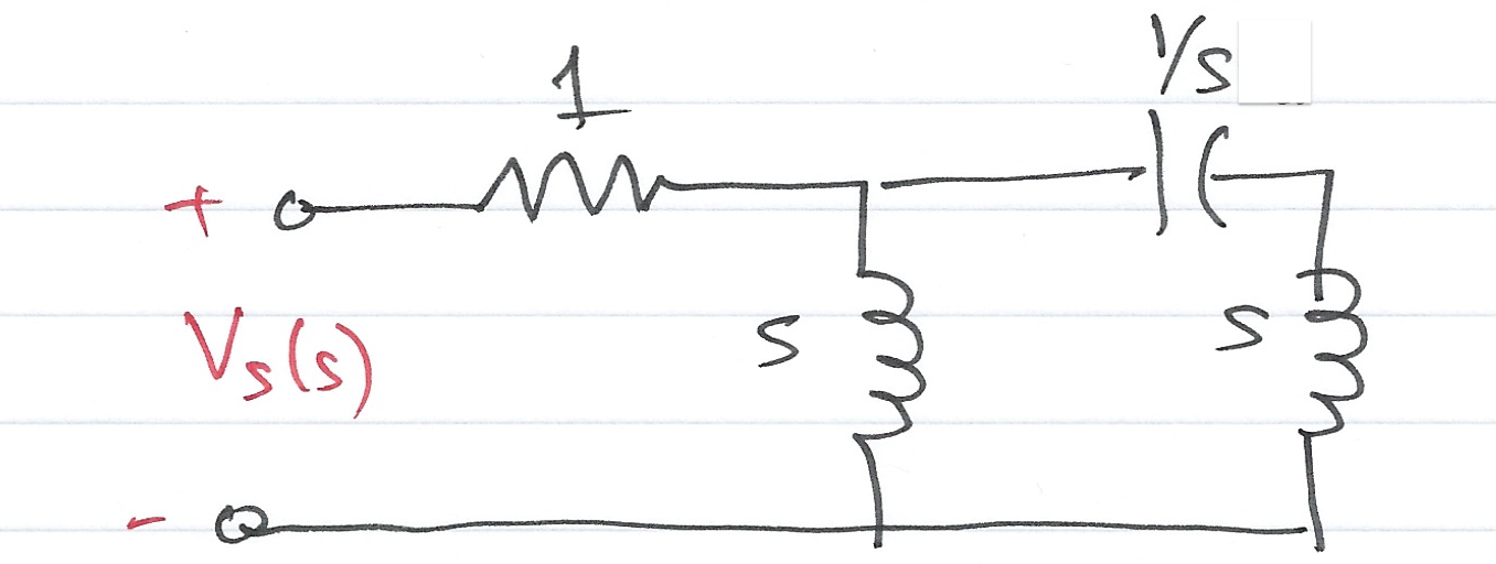
Find $Z(s)$ using:
- nodal analysis
- successive combinations of series and parallel impedances
Complex Admittance Y(s)
Consider the $s$-domain GLC parallel circuit shown below where the initial conditions are zero.
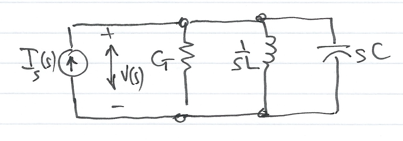
For this circuit
$$GV(s)+ \frac{1}{sL}V(s) + sCV(s) = I_s(s)$$
$$\left(G+ \frac{1}{sL} + sC\right)V(s) = I_s(s)$$
Defining the ratio $I_s(s)/V(s)$ as $Y(s)$ we obtain
$$Y(s)=\frac{I_s(s)}{V(s)} = G+ \frac{1}{sL} + sC = \frac{1}{Z(s)}$$
The $s$-domain voltage $V(s)$ can be found from
$$V(s) = \frac{I_s(s)}{Y(s)}$$
where
$$Y(s) = G + \frac{1}{sL} + sC.$$
$Y(s)$ is complex and is known as the complex input admittance of this GLC parallel circuit.
Example 5 - Do It Yourself
Compute $Z(s)$ and $Y(s)$ for the circuit shown below. All impedence values are in $\Omega$ (ohms). Verify your answers with MATLAB.
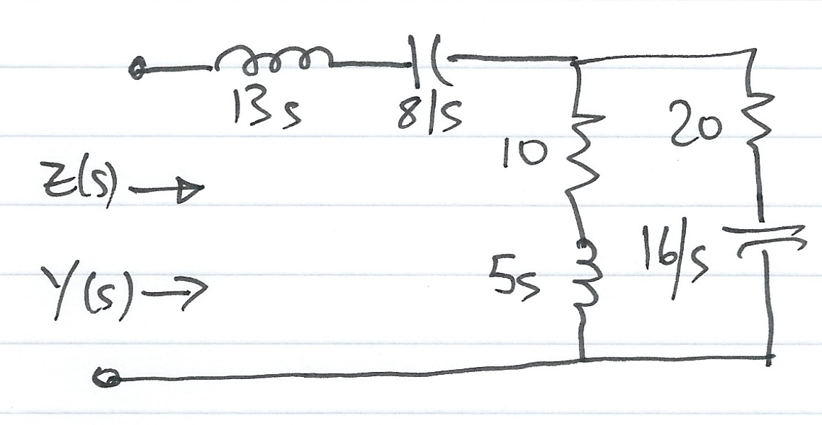
Answer 5
$$Z(s) = \frac{65s^4 + 490s^3 + 528s^2 + 400s + 128}{s(5s^2 + 30s + 16)}$$
$$Y(s) = \frac{1}{Z(s)} = \frac{s(5s^2 + 30s + 16)}{65s^4 + 490s^3 + 528s^2 + 400s + 128}$$
Matlab verification: solution5.m
Example 5: Verification of Solution
syms s;

z1 = 13*s + 8/s;
z2 = 5*s + 10;
z3 = 20 + 16/s;
z = z1 + z2 * z3 /(z2 + z3)
z =

13*s + 8/s + ((5*s + 10)*(16/s + 20))/(5*s + 16/s + 30)
z10 = simplify(z)
z10 =

(65*s^4 + 490*s^3 + 528*s^2 + 400*s + 128)/(s*(5*s^2 + 30*s + 16))
pretty(z10)
    4        3        2
65 s  + 490 s  + 528 s  + 400 s + 128
-------------------------------------
               2
         s (5 s  + 30 s + 16)
Admittance
y10 = 1/z10;
pretty(y10)
               2
         s (5 s  + 30 s + 16)
-------------------------------------
    4        3        2
65 s  + 490 s  + 528 s  + 400 s + 128